A twisting suction dredging robot with a crawler chassis swinging from side to side with self-correcting function
A technology that swings left and right and crawler chassis is applied in the field of robotics and can solve problems such as endangering the safety of the main canal
- Summary
- Abstract
- Description
- Claims
- Application Information
AI Technical Summary
Problems solved by technology
Method used
Image
Examples
Embodiment 1
[0039] This embodiment provides a crawler chassis swinging left and right twisting suction dredging robot with a self-correcting function, which can realize underwater harmless continuous movement and rapid dredging.
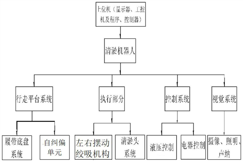
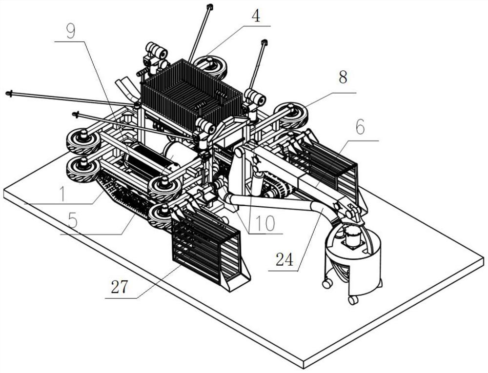
[0040] Such as figure 1 and figure 2 As shown, the dredging robot includes: a platform frame 9, a crawler chassis 1 arranged on the platform frame 9, a left and right swinging suction mechanism 6, a dredging mechanism 7, a pumping mechanism, a self-correcting unit and a control unit. Wherein the crawler chassis 1 is the walking platform of the dredging robot, and the left and right swing winch mechanism 6 and the dredging mechanism 7 are the execution parts of the dredging robot.
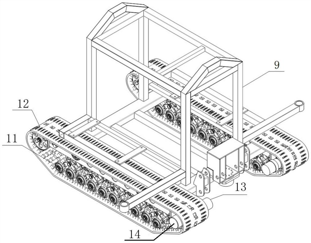
[0041] Such as image 3 As shown, the dredging robot uses a crawler chassis 1 as a walking mechanism, and the crawler chassis 1 includes: a crawler hub 11, a crawler belt 12, a motor A13 and a reducer 14; the platform frame 9 is the supporting structure of the entire robot, and the...
Embodiment 2
[0056] On the basis of the above-mentioned embodiment 1, in order to realize the positioning of the dredging robot in the culvert, an altimeter C38 is installed at the middle position of the front end of the platform frame 9, and the altimeter C38 is a long-range altimeter, and the self-positioning process is: The attitude sensor 35 monitors the inclination angle of the dredging robot in real time on the X-axis, Y-axis, and Z-axis (the Z-axis is consistent with the vertical direction) and feeds back to the upper computer on the ground, and the altimeter C38 feeds back the measurement data to the upper computer on the ground in real time machine; according to the attitude data monitored by the attitude sensor 35, it can be known that the dredging robot is currently in the lower slope section of the culvert entrance, the plane section or the upper slope section of the culvert exit. The sensor 35 provides data on the downward slope of the fuselage to the host computer, indicating ...
Embodiment 3
[0058] On the basis of the above-mentioned embodiment 1 or embodiment 2, a visual unit for monitoring the environment where the dredging robot is located is set on the platform frame 9, such as Figure 8 As shown, the visual unit includes: a front sonar 39 installed on the platform frame 9 , a front lighting camera unit 40 , a rear front lighting / camera unit 41 and a rear rear lighting / camera unit 42 . Wherein the front sonar 39 is arranged on the front end middle part of the platform frame 9, on the platform frame 9, the left and right sides of the front end of the collection basket 4 are respectively provided with a front lighting camera unit 40 with a lens facing the front, on the platform frame 9, the front light camera unit 40 of the collection basket 4 rear ends Rear front lighting / camera unit 41 and rear rear lighting / camera unit 42 are respectively arranged in the middle position, wherein the lens of rear front lighting / camera unit 41 faces forward, and the lens of rear...
PUM
 Abstract
Description
Claims
Application Information
 - R&D
- Intellectual Property
- Life Sciences
- Materials
- Tech Scout
- Unparalleled Data Quality
- Higher Quality Content
- 60% Fewer Hallucinations
Browse by: Latest US Patents, China's latest patents, Technical Efficacy Thesaurus, Application Domain, Technology Topic, Popular Technical Reports.
© 2025 PatSnap. All rights reserved.Legal|Privacy policy|Modern Slavery Act Transparency Statement|Sitemap|About US| Contact US: help@patsnap.com


