
Foundation construction anti-rolling and safe hydraulic crawler type long spiral drilling machine

A long auger drilling rig and foundation construction technology, applied in rotary drilling rigs, impact drilling, rotary drilling, etc., can solve the problems of long auger rigs lack of anti-sideways mechanism, long auger rigs sideways, poor flexibility, etc. , to achieve the effect of strong functionality, improved movement speed, and reasonable structure settings

Active Publication Date: 2019-04-05
韶关地质工程勘察院有限公司
View PDF8 Cites 0 Cited by
  • Summary
  • Abstract
  • Description
  • Claims
  • Application Information

AI Technical Summary

Problems solved by technology

[0003] 1. The walking mechanism of long auger drilling rigs on the market is hydraulic walking type. When moving forward, the hydraulic cylinders of the four outriggers support the ground, and the lower plate is lifted from the ground through the hydraulic system to drive the walking cylinder to realize the forward movement of the pile driver, and then retract The outriggers are lowered, and the chassis is pulled forward through the contraction of the hydraulic cylinder. After such repeated operations, the pile driver moves forward. This method moves slowly, and the pressure at the four outriggers is relatively high, and the bottom surface is prone to subsidence, resulting in long The auger drill sideways;
[0004] 2. The traditional hydraulic walking mechanism has poor flexibility and is prone to sideways when turning, and the traditional long auger lacks an effective anti-sideway mechanism

Method used


Image

  • Foundation construction anti-rolling and safe hydraulic crawler type long spiral drilling machine
  • Foundation construction anti-rolling and safe hydraulic crawler type long spiral drilling machine
  • Foundation construction anti-rolling and safe hydraulic crawler type long spiral drilling machine

Examples


Embodiment Construction

[0020] The following will clearly and completely describe the technical solutions in the embodiments of the present invention with reference to the accompanying drawings in the embodiments of the present invention. Obviously, the described embodiments are only some, not all, embodiments of the present invention. Based on the embodiments of the present invention, all other embodiments obtained by persons of ordinary skill in the art without making creative efforts belong to the protection scope of the present invention.

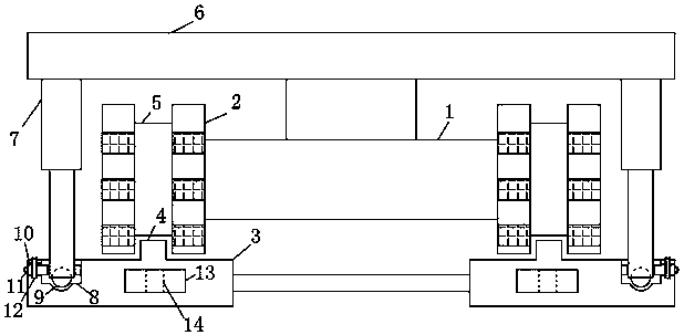
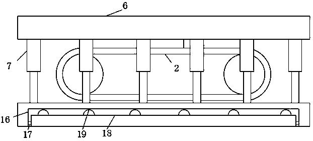
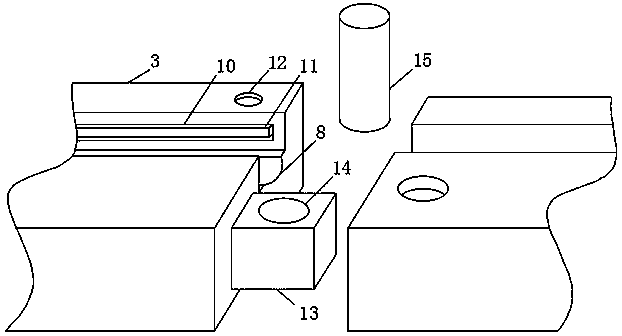
[0021] see Figure 1-4 , the present invention provides a technical solution: comprising a long auger drilling machine chassis 1, crawler belts 2, backing plates 3 and a fixing frame 6, the fixing frame 6, the long auger drilling machine chassis 1, crawler belts 2 and backing plates 3 are sequentially arranged from top to bottom, The outer side of the traveling wheel of the long auger drilling rig chassis 1 is provided with a crawler belt 2, and two crawler be...


PUM


Abstract

The invention discloses a foundation construction anti-rolling and safe hydraulic crawler type long spiral drilling machine. The foundation construction anti-rolling and safe hydraulic crawler type long spiral drilling machine comprises a long spiral drilling machine chassis, crawler belts, cushion plates and a fixing frame; the fixing frame, the long spiral drilling machine chassis, the crawler belts and the cushion plates are arranged sequentially from top to bottom; the outside of the walking wheels of the long spiral drilling machine chassis is provided with the two crawler belts; the twocrawler belts are distributed symmetrically relative to the center of the long spiral drilling machine chassis; the bottoms of the crawler belts are provided with a plurality of the cushion plates ina rectangular column structure which are connected end to end; the surfaces of the cushion plates are provided with sliding rails in a rectangular column structure, which are matched with sliding grooves formed in the surfaces of the crawler belts; the upper portion of the long spiral drilling machine chassis is provided with the fixing frame; the surface of a fixing plate is provided with hydraulic rods, which can effectively support the foundation construction anti-rolling and safe hydraulic crawler type long spiral drilling machine to avoid rolling of the foundation construction anti-rolling and safe hydraulic crawler type long spiral drilling machine.

Description

technical field [0001] The invention relates to the technical field of long auger drilling rigs, in particular to a hydraulic walking long auger drilling rig with anti-sideways safety type for foundation construction. Background technique [0002] Today, with the development and construction of high-speed rail, real estate, and new rural transformation, pile machinery has developed rapidly, especially long auger drilling rigs and rotary drilling rigs have achieved unprecedented development. The drilling method of long auger drilling rigs is one-time drilling. Drilling into the hole, the construction efficiency is high, and it is more and more widely used at present, but it still has the following disadvantages in actual use: [0003] 1. The walking mechanism of long auger drilling rigs on the market is hydraulic walking type. When moving forward, the hydraulic cylinders of the four outriggers support the ground, and the lower plate is lifted from the ground through the hydra...

Claims


Application Information

Patent Timeline
Patent Type & Authority Applications(China)
IPC IPC(8): E21B3/00E21B15/00E21B7/02
CPCE21B3/00E21B7/02E21B15/00
Inventor 林才鸿
Owner 韶关地质工程勘察院有限公司
Learn More