High-voltage capacitor voltage transformer with transient high-current overvoltage suppression function

A high-voltage capacitor and overvoltage suppression technology, applied in the direction of voltage/current isolation, etc., can solve the problems of long operation time, high cost, inconvenient maintenance, etc., to reduce transient high current, strong earthquake resistance, and convenient maintenance. Effect

Inactive Publication Date: 2019-04-05
毛运蓉
View PDF0 Cites 0 Cited by
  • Summary
  • Abstract
  • Description
  • Claims
  • Application Information

AI Technical Summary

Problems solved by technology

[0004] The disadvantages of the above methods are: 1. Inconvenient maintenance, the distance between the capacitor and the transformer is very long, and the maintenance is very inconvenient; 2, the cost is high, the distance between the capacitor and the transformer is at least 300km, the distance is very long, and the increase The maintenance cost is reduced; the cost of SF6 circuit breaker with excellent arc extinguishing performance is also high; 3. SF6 circuit breaker must be safe and reliable. When frequent operation of SF6 circuit breaker is required, SF6 circuit breaker cannot fail. Use a manually operated isolating switch to operate. The manual operation takes a long time, generally seconds or even minutes. If the operation time is long, the number of re-ignitions between fractures will be more, and the amplitude of large current and overvoltage will increase with the re-ignition. 4. Reduce the operating reliability of the transformer. When the isolating switch is manually operated, the large current and overvoltage amplitude are high, and the large current and overvoltage amplitude flowing through the transformer will also increase with the The increase will bring hidden dangers to the safe operation of the transformer and reduce the reliability of the transformer operation

Method used


Image

  • High-voltage capacitor voltage transformer with transient high-current overvoltage suppression function

Examples


Embodiment Construction

[0021] Below in conjunction with embodiment the present invention is described in further detail:

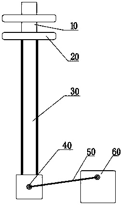
[0022] The high-voltage capacitive pressure transformer of the present invention includes a voltage equalizing ring 20, a capacitive voltage divider 30, a support base 40, and an electromagnetic unit 60, and it also includes an overvoltage suppression device 10 for a transient large current, and the overvoltage suppression device 10 is arranged on the top of the capacitive voltage divider 30, and the overvoltage suppression device 10 is connected in series with the capacitive voltage divider 30 through the pressure equalizing ring 20; a channel steel reinforcing rib is provided on the supporting base 40, and is fixedly connected with the capacitive voltage divider 30; The electromagnetic unit 60 is a cylindrical steel structure with 4 to 8 installation holes, and a reinforcing device is arranged around each installation hole. The support base 40 is a cylindrical steel structure ...


PUM


Abstract

The invention discloses a high-voltage capacitor voltage transformer with a transient high-current overvoltage suppression function. The high-voltage capacitor voltage transformer comprises a gradingring, a capacitive divider, a supporting base and an electromagnetic unit, and further comprises an overvoltage suppression device for transient high-current. The overvoltage suppression device is provided at the top of the capacitive divider and connected with the capacitive divider in series through the grading ring. A channel steel reinforcing rib is provided on the supporting base fixedly connected with the capacitive divider. The electromagnetic unit is of a cylindrical steel structure, and is provided with four to eight mounting holes, and each mounting hole is provided with a reinforcing device around. The high-voltage capacitor voltage transformer has the advantages that the high-voltage capacitor voltage transformer has high mechanical strength, that is, high bending resistance, and high anti-seismic capacity; maintaining convenience; and reduced manufacturing cost; can be operated by a manually operated isolation switch; can reduce the transient high-current flowing through the transformer and the overvoltage amplitude; and can improve the operation reliability of the transformer.

Description

technical field [0001] The invention relates to a high-voltage capacitive voltage transformer, in particular to a high-voltage capacitive voltage transformer with the function of suppressing instantaneous large current and overvoltage. Background technique [0002] High-voltage capacitive voltage transformers are used in high-voltage, ultra-high voltage and ultra-high voltage power systems, connected between line and ground, and used for metering, measurement, and relay protection. In high-voltage, ultra-high voltage and ultra-high voltage long-distance transmission lines, in order to increase the transmission capacity, capacitors are often connected in series in the transmission line. When the capacitor is switched or switched, there will be a short-term transient oscillation process, which will generate large current and overvoltage. When the transformer is close to the capacitor, the transient large current and overvoltage will flow through the transformer, causing damag...

Claims


Application Information

Patent Timeline
Patent Type & Authority Applications(China)
IPC IPC(8): G01R15/16
CPCG01R15/16
Inventor 毛运蓉
Owner 毛运蓉
Why Eureka
Try Eureka