
Unmanned aerial vehicle laser navigation system based on position sensitive detector

A laser navigation and UAV technology, applied in the field of UAV navigation, can solve the problem that the navigation process is easily affected by light, distance, exposure, background, etc., the GPS/IMU navigation positioning accuracy is insufficient, and the detection angle of the four-quadrant photoelectric sensor is small. and other problems, to achieve the effect of wide detection angle, high miniaturization, and avoiding external interference

Pending Publication Date: 2019-04-05
NANJING UNIV OF SCI & TECH
View PDF4 Cites 5 Cited by
  • Summary
  • Abstract
  • Description
  • Claims
  • Application Information

AI Technical Summary

Problems solved by technology

[0011] Aiming at the problems existing in common UAV positioning and navigation technology: 1) Simple GPS / IMU navigation positioning accuracy is insufficient, easily affected by the environment, and there are cumulative errors; 2) Artificial marker navigation and ground wide-angle camera navigation must be pre-set The navigation point cannot achieve long-distance non-contact navigation; 3) The image processing navigation process is easily affected by light, distance, exposure, background, etc.; 4) The four-quadrant photoelectric sensor has a small detection angle, dead zone, and requires pre-alignment The laser reflection spot makes the UAV guidance inflexible and other problems

Method used


Image

  • Unmanned aerial vehicle laser navigation system based on position sensitive detector
  • Unmanned aerial vehicle laser navigation system based on position sensitive detector
  • Unmanned aerial vehicle laser navigation system based on position sensitive detector

Examples


Embodiment Construction

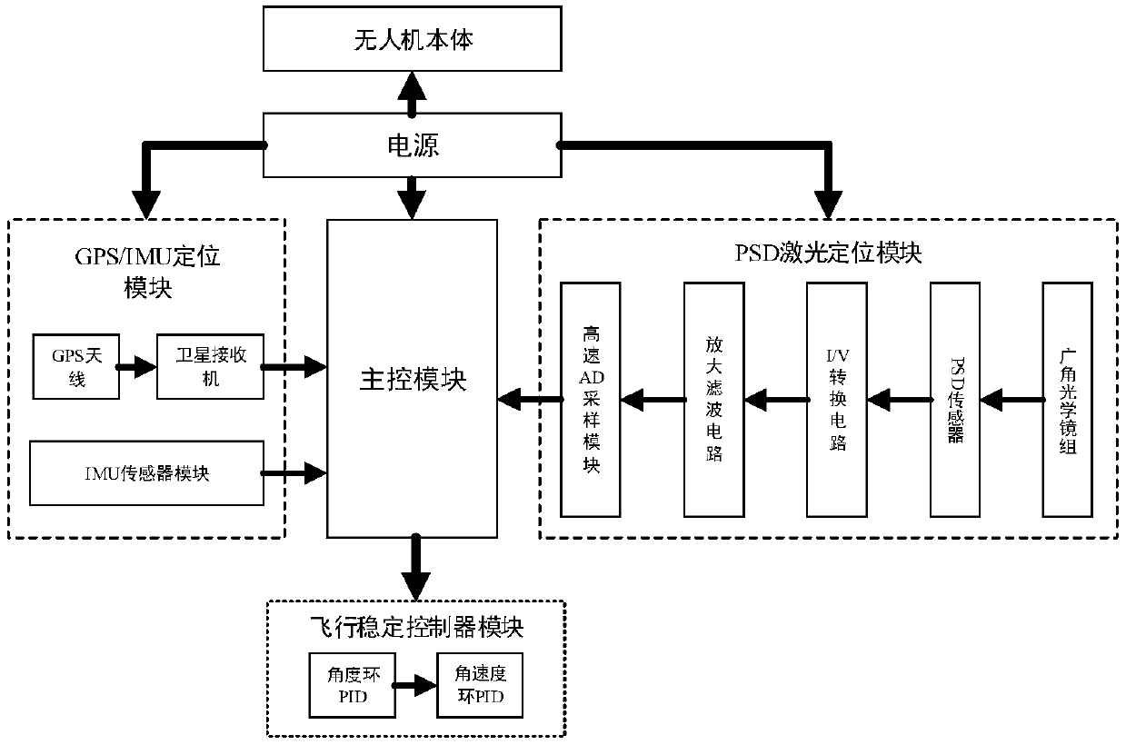
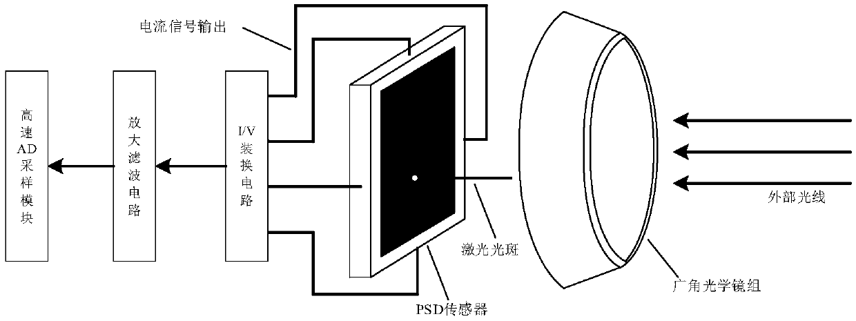
[0030] combine figure 1 , The present invention provides a UAV laser navigation system based on a position-sensitive detector, including a UAV body, a power supply, a GPS / IMU positioning module, a PSD laser positioning module, a main control module and a flight stability controller module. in:

[0031] (1) The power supply supplies power to the GPS / IMU positioning module, the PSD laser positioning module, the main control module and the flight stability controller module.

[0032] (2) The GPS / IMU positioning module is installed on the unmanned aerial vehicle body, and is made up of GPS antenna, satellite receiver and IMU sensor module, and wherein satellite receiver is connected with GPS antenna, main control module respectively by signal line, and The satellite positioning signal is received through the GPS antenna, and the signal is transmitted to the main control module. The IMU sensor module is connected to the main control module through the signal line, and the acceler...


PUM


Abstract

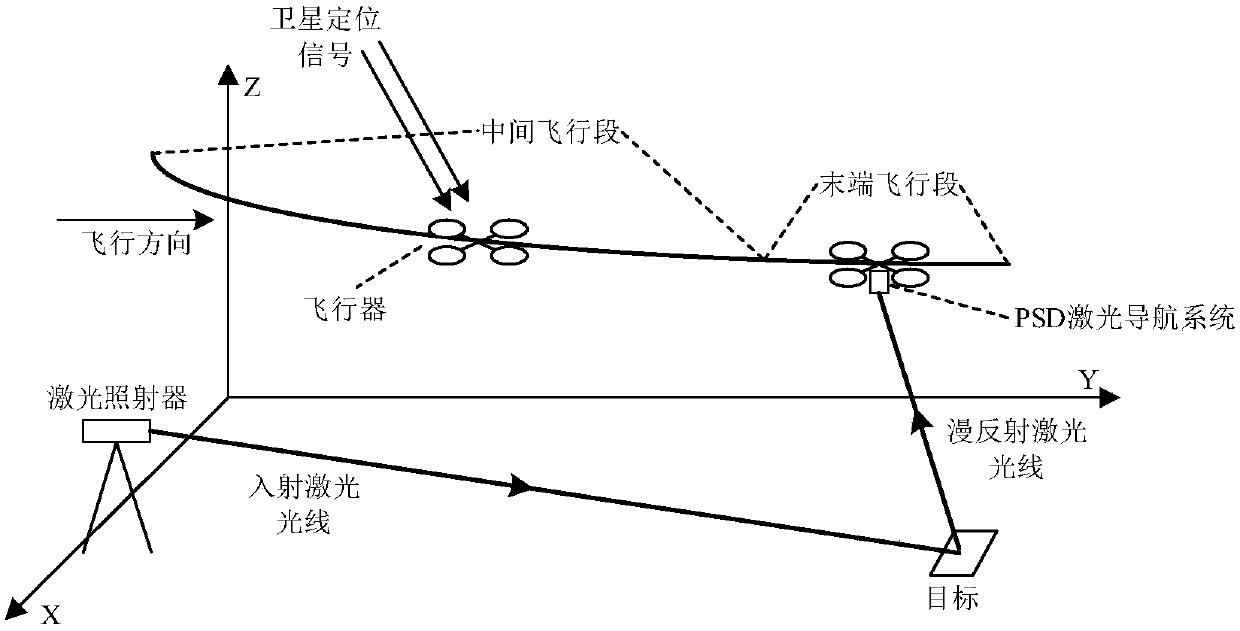
The invention discloses an unmanned aerial vehicle laser navigation system based on a position sensitive detector. The unmanned aerial vehicle laser navigation system comprises an unmanned aerial vehicle body, a power supply, a GPS (Global Positioning System) / IMU (Inertial Measurement Unit) positioning module, a PSD (Position Sensitive Detector) laser positioning module, a master control module and a flight stability controller module, wherein the GPS / IMU positioning module comprises a GPS antenna, a satellite receiver and an IMU sensor module. The PSD laser positioning module comprises a wide-angle optical lens group, a PSD sensor, an I / V conversion circuit, an amplifying and filtering circuit and a high-speed AD (Analog to Digital) sampling module. The GPS antenna is connected with the satellite receiver; the PSD laser positioning system is arranged at the bottom of an unmanned aerial vehicle in a vertical direction; the wide-angle optical lens group is arranged in front of the PSD sensor; the PSD sensor is connected with the I / V conversion circuit; I / V conversion circuit is connected with the high-speed AD sampling module; and the satellite receiver, the IMU sensor module, and the high-speed AD sampling module are respectively connected with a navigation positioning master control module separately. According to the unmanned aerial vehicle laser navigation system based on the position sensitive detector provided by the invention, GPS / IMU coarse positioning is combined with PSD laser fine positioning, so as to improve the precision and robustness of a navigation positioning system, and realize an accurate navigation operation of the unmanned aerial vehicle.

Description

technical field [0001] The invention belongs to the technical field of unmanned aerial vehicle navigation, in particular to an unmanned aerial vehicle laser navigation system based on a position sensitive detector (PSD). Background technique [0002] The navigation and positioning system is the core component of the UAV navigation technology, and it is the key for the UAV to complete the preset route flight, fixed-point take-off and landing, and hovering actions. At present, most UAV navigation systems use the combination of Global Positioning System (Global Positioning System, GPS) navigation and Micro-Electro-Mechanical System (MEMS) inertial navigation, that is, while receiving satellite positioning signals during work, The real-time position and attitude information of the UAV is obtained by using the combination of inertial navigation to obtain the relative position relationship with the target. However, the positioning accuracy of commercial GPS is on the order of 10m...

Claims


Application Information

Patent Timeline
IPC IPC(8): G01S19/48G01S19/49
CPCG01S19/48G01S19/49
Inventor 李伟伟于纪言
Owner NANJING UNIV OF SCI & TECH
Learn More