A three-phase reactive power compensation device without a DC energy storage unit

A technology of energy storage unit and compensation device, which is applied in the direction of reactive power compensation, reactive power adjustment/elimination/compensation, circuit devices, etc., and can solve the problem of small reactive compensation current adjustment range, increased device size, single research content, etc. problem, to achieve the effect of improving the quality of capacitive reactive current waveform, improving the adjustment range and high reliability

Active Publication Date: 2022-02-18
NANJING UNIV OF SCI & TECH
View PDF7 Cites 0 Cited by
  • Summary
  • Abstract
  • Description
  • Claims
  • Application Information

AI Technical Summary

Problems solved by technology

[0004] The current research on the new static var compensator is based on the step-down AC-AC converter, the research content is single, and in the case of a certain reactive power compensation capacitor, the adjustment range of the reactive power compensation current provided by it is small; The static var compensator of the push-pull forward direct AC-AC converter, but it uses a large number of power switch tubes, which increases the volume of the device, increases the complexity of the control, and is not easy to modularize. Therefore, the new reactive power compensation topology The introduction of reactive power, the expansion of reactive power adjustment range, and the corresponding control technology need to be further studied.

Method used


Image

  • A three-phase reactive power compensation device without a DC energy storage unit
  • A three-phase reactive power compensation device without a DC energy storage unit
  • A three-phase reactive power compensation device without a DC energy storage unit

Examples


Embodiment

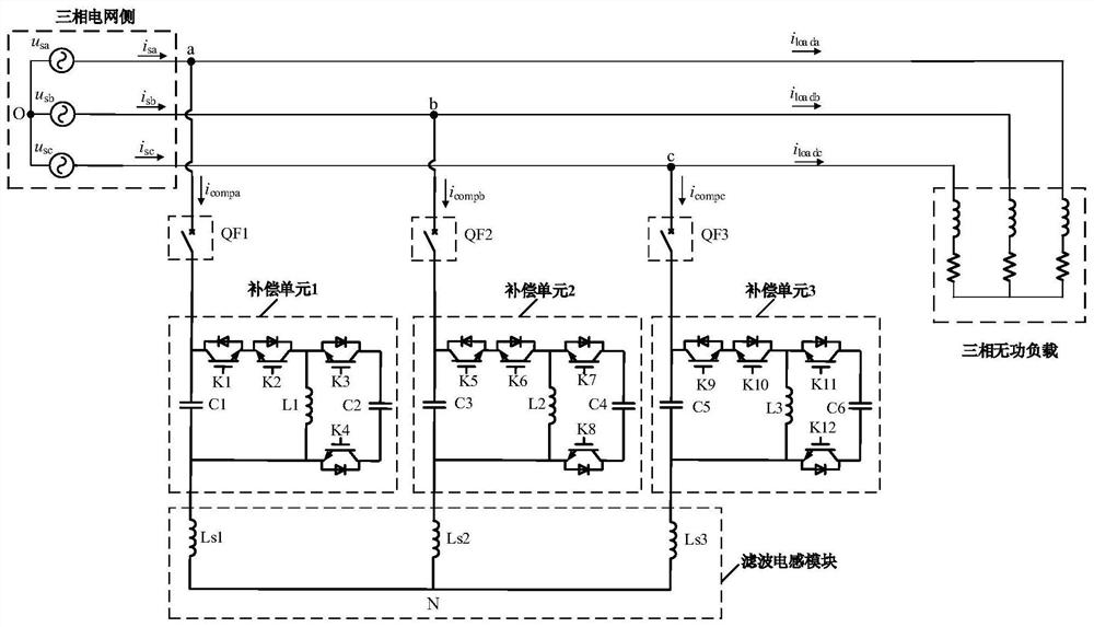
[0023] like figure 1 As shown, a three-phase reactive power compensation device without a DC energy storage unit, the main power topology consists of three identical circuit breakers, three identical compensation units and a filter inductor module. Each compensation unit includes two AC capacitors, four IGBT tubes and an inductor, and the filter inductor module is composed of three star-connected inductors.

[0024] One end of the first circuit breaker QF1 is connected between the phase a power supply and the phase a inductive reactive load.

[0025] The first compensation unit includes a first capacitor C1, a first IGBT transistor K1, a second IGBT transistor K2, a third IGBT transistor K3, a fourth IGBT transistor K4, a first inductor L1 and a second capacitor C2. In the first compensation unit, one end of the first capacitor C1 serves as one end of the first compensation unit and is connected to the other end of the first circuit breaker QF1. One end of the first capacito...


PUM


Abstract

The invention discloses a three-phase reactive power compensation device without a DC energy storage unit, which comprises three identical circuit breakers, three identical compensation units and a filter inductance module. The filter inductance module consists of three star-shaped connected inductors Composition; one end of the first circuit breaker is connected between the a-phase power supply and the a-phase inductive reactive load, the other end is connected to the first compensation unit, and one end of the second circuit breaker is connected to the b-phase power supply and the b-phase inductive reactive load. The other end of the third circuit breaker is connected between the c-phase power supply and the c-phase inductive reactive load, and the other end is connected to the third compensation unit; the other end of the three compensation units One end is respectively connected to the three inductors of the filter inductor module. The invention does not need a DC energy storage unit, and the capacitors used are all AC capacitors. The whole device has high reliability, long service life, easy modular manufacturing and high cost performance.

Description

technical field [0001] The invention relates to a reactive power compensation technology of an electric power system, in particular to a three-phase reactive power compensation device without a DC energy storage unit. Background technique [0002] With the rapid development of the economy, reactive power has become an important physical quantity in the power system. Most network components and loads need to consume reactive power. It is obviously unreasonable for these reactive power to be provided by generators and to achieve long-distance transmission. It is even impossible, and the reasonable method is to set up reactive power compensation devices where reactive power needs to be consumed, and absorb (or send out) reactive power to the grid. [0003] For reactive power compensation devices, the earliest ones are synchronous condensers and fixed capacitor banks (Fixed CapacitorBank, FC). With the development of power electronics technology, the Static VAR Compensator (SVC...

Claims


Application Information

Patent Timeline
Patent Type & Authority Patents(China)
IPC IPC(8): H02J3/18
CPCH02J3/1821H02J3/1835Y02E40/30
Inventor 吕广强戚向阳陈曦许峰刘潇逸
Owner NANJING UNIV OF SCI & TECH
Why Eureka
Try Eureka