Rapid casting part cooling device for casting

A technology for rapid cooling and casting, applied in the field of casting, can solve the problems of low degree of automation, affecting the cooling efficiency of castings, etc., to achieve the effect of good cooling effect, convenient cooling work, and improving the level of automation

Inactive Publication Date: 2019-04-09
青岛全程源机械有限公司
View PDF7 Cites 4 Cited by
  • Summary
  • Abstract
  • Description
  • Claims
  • Application Information

AI Technical Summary

Problems solved by technology

[0003] Chinese patent (publication number: CN206405419U) discloses a cooling chamber for castings. In this patent, a fan, an air outlet window, a second air inlet, a ventilation pipe, a first air inlet, and a cooling fan are used to rise the cooling chamber by hot air. The principle of air sinking realizes the cooling of castings, but during the cooling process, castings need to be placed manually, and the degree of automation is low, which seriously affects the cooling efficiency of castings

Method used


Image

  • Rapid casting part cooling device for casting
  • Rapid casting part cooling device for casting
  • Rapid casting part cooling device for casting

Examples


Embodiment 1

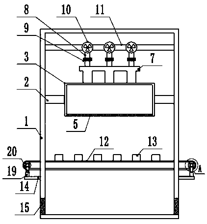
[0021] see Figure 1-3 , a fast cooling device for castings, comprising a device box 1, a fixing frame 2 is fixedly connected above the inner walls of the left and right sides of the device box 1, and a cooling box 3 is fixedly installed inside the middle of the fixing frame 2, and the left and right sides of the cooling box 3 A condenser 4 is fixedly installed on the inner wall of the side, and a breathable plate 5 is fixedly connected to the box below the cooling box 3, and the breathable plate 5 is located directly above the conveyor belt 12, and an exhaust port is provided under the box body on the left and right sides of the device box 1 15.

[0022] Specifically, a connecting pipeline 7 is fixedly connected to the middle of the box above the cooling box 3, and the lower end of the connecting pipeline 7 is fixedly installed with an air nozzle 6, and the upper surface of the connecting pipeline 7 is fixedly connected to a fan pipe 8. The upper end of the fan duct 8 is con...

Embodiment 2

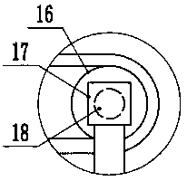
[0024] see Figure 4 The difference between the second embodiment and the first embodiment is that a chute 21 is provided in the middle of the top of the support base 19, a spring 22 is fixedly connected to the lower surface of the chute 21, and a fixed rod 20 is fixedly connected to the upper end of the spring 22, and the fixed rod 20 It is connected with the surface of the left and right sides of the chute 21 in a contact manner. The conveyor belt 12 is prone to shaking during the transmission process. The spring 22 is installed inside the chute 21 to make the conveyor belt 12 more stable during the transmission process and ensure the safety of the conveyor belt 12. run.

[0025] This fast cooling device for castings is equipped with a condenser 4 in the cooling box 3, so that cold air is generated in the cooling box 3, and the air nozzle 6 is blown by the fan 10, and the cold air is blown to the surface of the casting 13, so that The casting 13 is cooled quickly, the cooli...


PUM


Abstract

The invention discloses a rapid casting part cooling device for casting and relates to the technical field of casting. The rapid casting part cooling device comprises a device box. A fixing frame is fixedly connected above the inner wall of the left side and the inner wall of the right side of the device box. A cooling box is fixedly installed in the middle of the fixing frame. Condensers are fixedly installed on the inner wall of the left side and the inner wall of the right side of the cooling box. A connecting pipeline is fixedly connected into the middle of a box body above the cooling box. A wind nozzle is fixedly installed at the lower end of the connecting pipeline. A fan pipe is fixedly connected to the upper surface of the connecting pipeline. A fan is connected to the upper end of the fan pipe. A filter screen is fixedly installed in the middle of the fan pipe. A base is fixedly connected below the outer wall of the left side and the outer wall of the right side of the devicebox. According to the rapid casting part cooling device, a casting part can be cooled rapidly, the cooling effect is good, by means of design of a conveying belt, the casting part can be conveyed automatically, cooling work of the casting part is facilitated, the automation level is improved, the cooling efficiency of the casting part is improved greatly, and practicality is high.

Description

technical field [0001] The invention relates to the technical field of casting, in particular to a casting rapid cooling device for casting. Background technique [0002] Casting is a kind of metal thermal processing technology mastered by human beings earlier, with a history of about 6,000 years. China has entered the heyday of bronze castings between 1700 BC and 1000 BC, and the craftsmanship has reached a very high level. Casting is a method in which liquid metal is poured into a casting cavity adapted to the shape of the part, and after it is cooled and solidified, the part or blank is obtained. Most of the cast substances are metals that are originally solid but heated to liquid (eg copper, iron, aluminum, tin, lead, etc.), and the material of the mold can be sand, metal or even ceramics. Depending on the requirements, the methods used will vary. [0003] Chinese patent (publication number: CN206405419U) discloses a cooling chamber for castings. In this patent, a fan...

Claims


Application Information

Patent Timeline
Patent Type & Authority Applications(China)
IPC IPC(8): B22D30/00
CPCB22D30/00
Inventor 鹿巨栋
Owner 青岛全程源机械有限公司
Why Eureka
Try Eureka