Box type polyurethane ceramic liner plate preparing method and liner plate manufactured through box type polyurethane ceramic liner plate preparing method

A ceramic liner and polyurethane technology, applied in the field of materials, can solve the problems that the effect of impact resistance is not very good, the impact resistance of the liner is affected, and the wear resistance of the surface of the liner is affected, so as to achieve a simple manufacturing process and increase elasticity. , the effect of reasonable structure

Inactive Publication Date: 2019-04-09
余博
View PDF7 Cites 2 Cited by
  • Summary
  • Abstract
  • Description
  • Claims
  • Application Information

AI Technical Summary

Problems solved by technology

[0003] The applicant applied for the patent number 200820192141.8 at the China Patent Office on November 6, 2008, and the invention name is a utility model patent for a box-type impact-resistant wear-resistant ceramic lining. This patent discloses a box-type impact lining , the liner is embedded in a metal box with a number of ceramic sheets, which overcomes the shortcoming of the non-wearable metal parts through the ceramic sheets, but the patent does not limit the shape of the ceramic sheets, because the thickness of the ceramic sheets is generally not large, Therefore, if ordinary ceramic sheets are directly connected, the contact surface between the side of the ceramic sheet and the bonding rubber is small, and the bonding is not very firm, which will affect its impact resistance. If more vulcanized rubber is used, the gap between the two ceramic sheets It will be very large, so the effect of impact resistance is not very good, and it will affect the wear resistance of the surface of the liner; in addition, because the outer box of the liner in this patent is a metal box, its bottom surface is directly in contact with the hopper, material There is no buffer between warehouses and other connections, which will also affect the impact resistance of the liner

Method used


Image

  • Box type polyurethane ceramic liner plate preparing method and liner plate manufactured through box type polyurethane ceramic liner plate preparing method
  • Box type polyurethane ceramic liner plate preparing method and liner plate manufactured through box type polyurethane ceramic liner plate preparing method
  • Box type polyurethane ceramic liner plate preparing method and liner plate manufactured through box type polyurethane ceramic liner plate preparing method

Examples


Embodiment Construction

[0029] The following will clearly and completely describe the technical solutions in the embodiments of the present invention with reference to the accompanying drawings in the embodiments of the present invention. Obviously, the described embodiments are only some of the embodiments of the present invention, not all of them. Based on the embodiments of the present invention, all other embodiments obtained by persons of ordinary skill in the art without making creative efforts belong to the protection scope of the present invention.

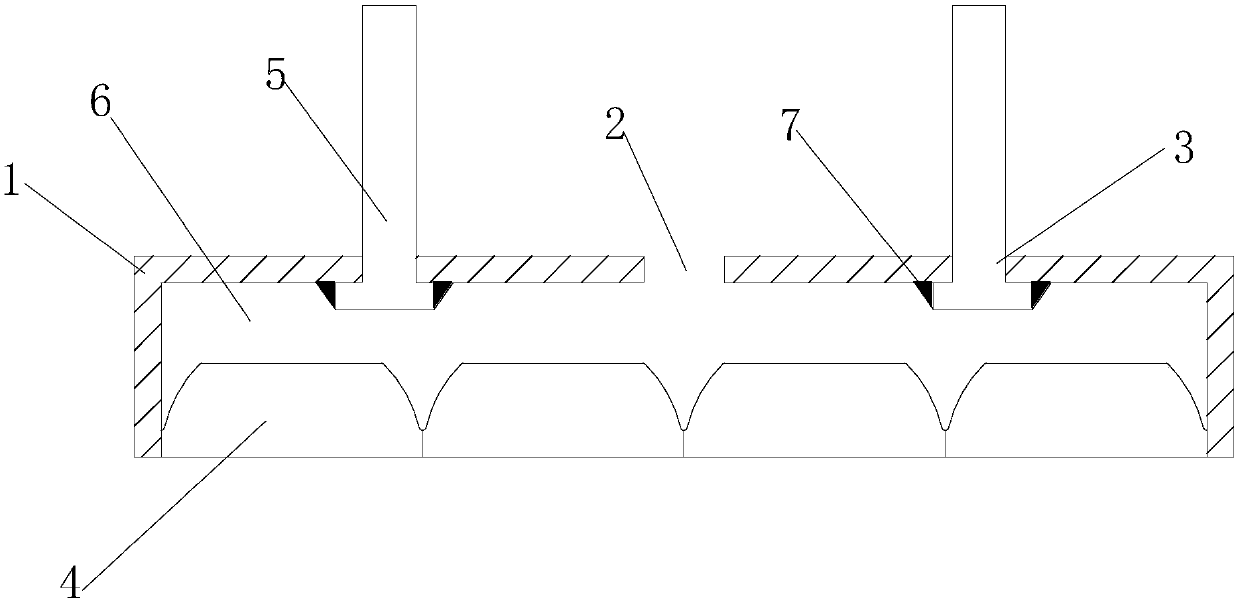
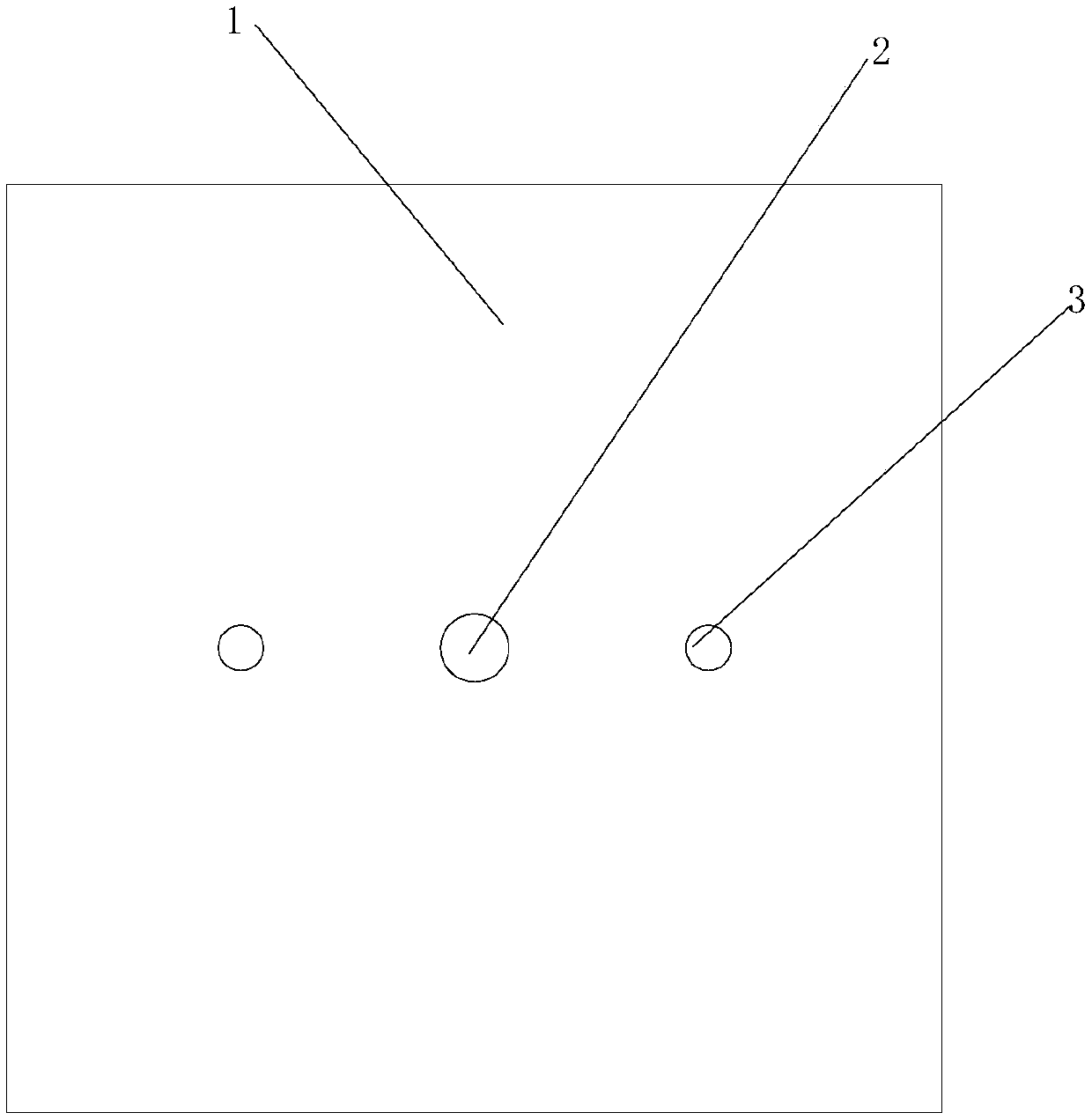
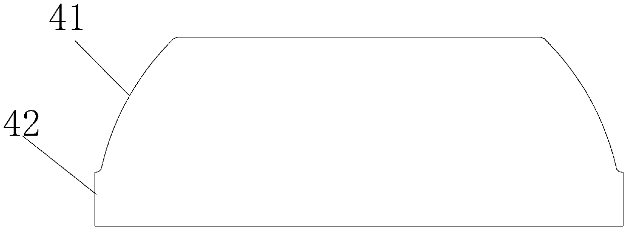
[0030] see Figure 1-Figure 3 , the present invention provides a technical solution:

[0031] A method for preparing a box-type polyurethane ceramic liner, comprising the following specific steps:

[0032] Step 1: Use a laser cutting machine to cut the steel plate into the shape of the shell expansion, cut out the bolt holes for installing the bolts on the bottom plate of the steel shell corresponding to the position where the bolts need to be i...


PUM

PropertyMeasurementUnit
densityaaaaaaaaaa
hardnessaaaaaaaaaa

Abstract

The invention provides a box type polyurethane ceramic liner plate preparing method and a liner plate manufactured through the box type polyurethane ceramic liner plate preparing method. The liner plate comprises a steel shell. A glue injection hole is formed in a bottom face steel plate of the steel shell and formed in the bottom face steel plate. Corundum ceramic blocks are tightly placed on theupper surface of the steel shell at equal intervals. Cavities between the bottoms of the corundum ceramic blocks and the inner side wall of the bottom face steel plate are filled with a polyurethanematerial layer for fixedly connecting the corundum ceramic blocks with the steel shell. The manufacturing technology is simple, the structure is reasonable, the liner plate is high in abrasion resistance and can bear powerful impacts for a long term, the production cost is low, and the comprehensive usage expense can be reduced for users.

Description

technical field [0001] The invention relates to the field of materials, in particular to a method for preparing a box-type polyurethane ceramic lining board and the manufactured lining board. Background technique [0002] In the material conveying systems of industries such as electric power, metallurgy, steel, and bulk cargo terminals, some parts such as hoppers, silos, etc., materials with a diameter of about 10 cm fall from a height of more than 3 meters, and the impact force is very large. At present , This part mostly uses metal parts processed from steel as the bearing carrier. Due to the limited wear resistance of these materials, parts such as silos and hoppers are very easy to wear and tear, which makes the service life of silos and hoppers short and frequent replacement. This has not only increased production costs, but also increased the labor intensity of workers. In actual production, there is an urgent need for a liner that has good wear resistance and can wit...

Claims


Application Information

Patent Timeline
Patent Type & Authority Applications(China)
IPC IPC(8): B65D90/04F16B11/00
Inventor 余博
Owner 余博
Why Eureka
Try Eureka