Jet flow-type ROV-type (Remote Operated Vehicle-type) trencher used for rapidly clearing sludge above offshore pipeline
A trencher, sea pipe technology, applied in the direction of earthmoving machine/shovel, construction, etc., can solve the problems of heavy trencher, high power and cost, and the system cannot be self-stabilized, and achieves high operating efficiency and saving. Operating cost, effect of expanding cleaning capacity
- Summary
- Abstract
- Description
- Claims
- Application Information
AI Technical Summary
Problems solved by technology
Method used
Image
Examples
Embodiment 1
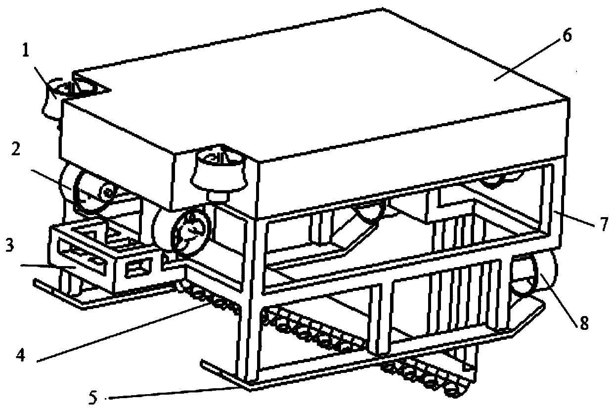
[0050] Implementation 1: If figure 1As shown, the jet-type ROV trencher is divided into the following parts as a whole: the spray arm is arranged on the front side of the trencher, and the distance and pitch angle of the two spray arms can be adjusted according to the actual task requirements to achieve the best effect ;The pipeline detection sensor adopts the TSS pipe cable detection system to detect the burial depth of the sea pipe and the horizontal offset of the sea pipe relative to the ROV, and provide accurate sea pipe position information for the automatic cleaning of the jet-assisted ROV trencher; the ROV body The whole is an integrated metal frame, the structure is as simple and light as possible, providing installation and support for each component of the system; the buoyancy material provides a certain buoyancy for the jet-assisted ROV trencher to ensure the safe and stable operation of the ROV underwater; The propeller system is composed of 6 propellers horizontal...
Embodiment 2
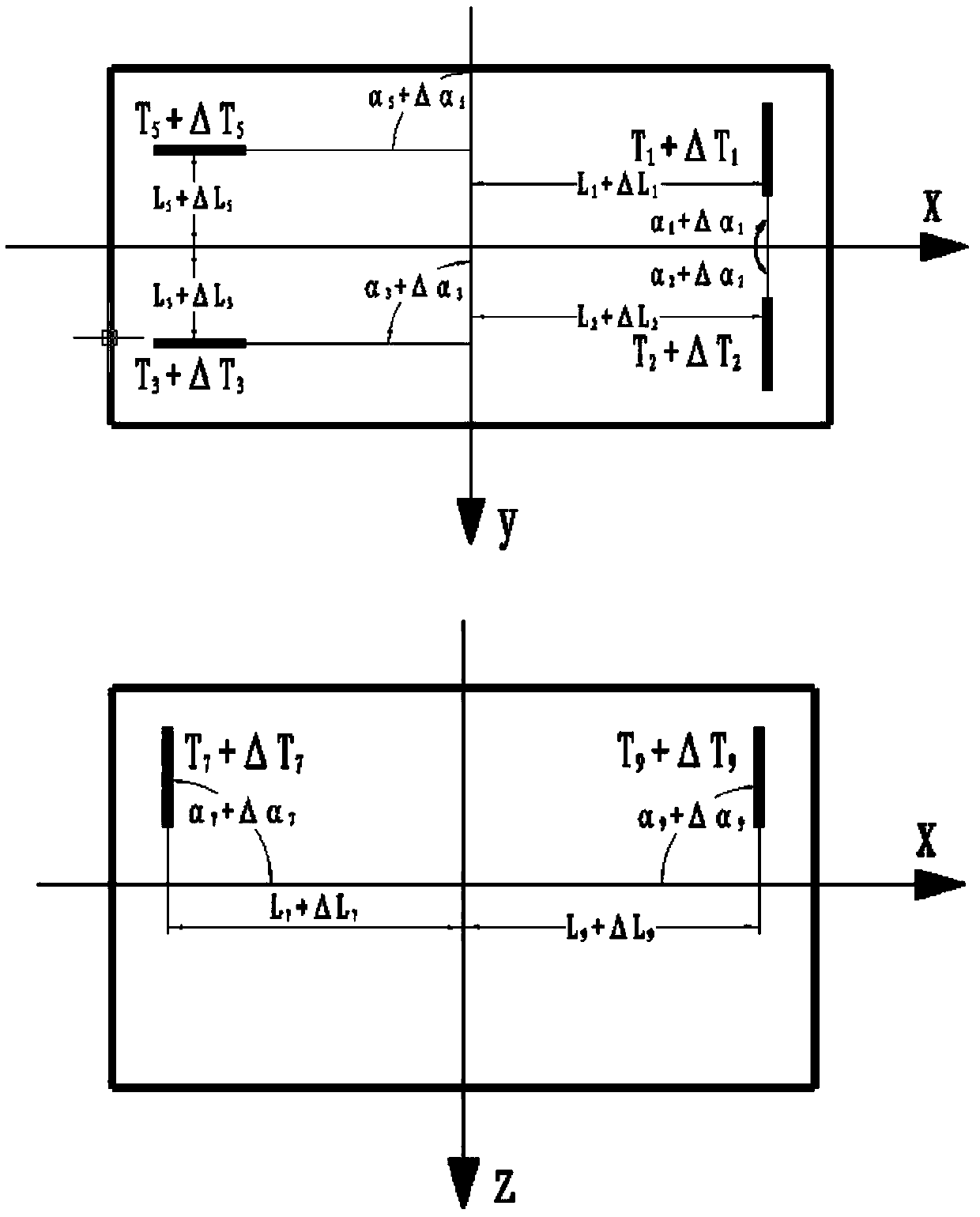
[0051] Implementation 2: If figure 2 As shown, the jet-type ROV trencher system has a total of 10 thrusters, including 4 horizontal thrusters, 4 longitudinal thrusters, and 2 lateral thrusters. The thrust formula generated by each propeller of the jet-type ROV trencher system is as follows:
[0052]
[0053]
[0054]
[0055]
[0056]
[0057] The propeller calibration test can be carried out according to each propeller, and the parameters can be calibrated, laying the foundation for the calculation and dynamic modeling of the whole machine.
Embodiment 3
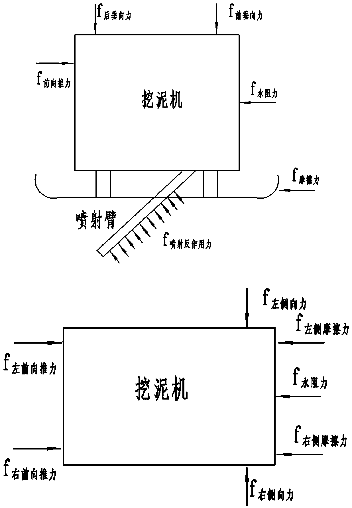
[0058] Implementation 3: If image 3 As shown, the thrust of each propeller is sorted out, the mass of the dredger is set to m, and the forward motion acceleration is a, then:
[0059] ma=f 左前向推力 + f 右前向推力 -f 左侧摩擦力 -f 右侧摩擦力 -f 水阻力 -f 喷射反作用力 *cos45 (6)
[0060] In order to ensure that the dredger can move in the direction of the detection sea pipe, it can be adjusted through the lateral thruster. If the current heading is maintained, the following formula is given:
[0061] f 左侧向力 = f 右侧向力 (7)
[0062] In order to ensure the normal operation of the dredger, it is necessary to ensure that the dredger is in contact with the seabed, as follows:
[0063] f 后垂向力 + f 前垂向力 +mg=f 喷射反作用力 cos45 (8)
PUM
 Abstract
Description
Claims
Application Information
 - Generate Ideas
- Intellectual Property
- Life Sciences
- Materials
- Tech Scout
- Unparalleled Data Quality
- Higher Quality Content
- 60% Fewer Hallucinations
Browse by: Latest US Patents, China's latest patents, Technical Efficacy Thesaurus, Application Domain, Technology Topic, Popular Technical Reports.
© 2025 PatSnap. All rights reserved.Legal|Privacy policy|Modern Slavery Act Transparency Statement|Sitemap|About US| Contact US: help@patsnap.com


