Nuclear power plant spent fuel storage tank

A spent fuel and nuclear power plant technology, applied in the field of nuclear power, can solve the problems of difficult underwater installation and positioning of the cover plate of the horizontal spent fuel storage tank, complex cutting and retrieval operations of the horizontal spent fuel storage tank, and increased radiation dose levels, etc. Achieve the effect of avoiding the problem of equipment jamming and damage, avoiding the difficulty of positioning, simplifying the difficulty of processing, manufacturing and installation

Active Publication Date: 2020-09-25
CHINA NUCLEAR POWER DESIGN COMPANY +3
View PDF7 Cites 1 Cited by
  • Summary
  • Abstract
  • Description
  • Claims
  • Application Information

AI Technical Summary

Problems solved by technology

[0004] (1) It is difficult to install and locate the cover plate of the horizontal spent fuel storage tank underwater
[0005] The existing horizontal spent fuel storage tank cover includes shielding cover, inner layer and outer layer cover. Since the inflatable drainage hole assembly and the shell are completely welded and connected, the shielding cover and inner layer cover must be designed with a special-shaped cover. , There are difficulties in installation and positioning and jamming problems in special-shaped parts
[0006] (2) The operation of cutting and retrieving the horizontal spent fuel storage tank is complex
[0010] c) The cover plate of the inflation and drainage holes is completely covered by the cover plate, making it difficult to accurately locate and punch holes;
[0011] d) The welding seam of the internal cover plate is an irregular and special-shaped welding seam. It is necessary to configure cutting machines for cutting circular welds and irregular and special-shaped welding seams respectively. The operation is complicated and the radiation dose level is increased.
[0012] (3) The double-layer independent welding cover plate needs to be hoisted and unloaded welding equipment several times
[0013] The existing horizontal spent fuel storage tank adopts a multi-layer independent cover plate design. After the welding operation of the inner layer cover plate is completed, the welding machine needs to be disassembled first, then the outer layer cover plate is hoisted to the storage tank, and then the welded The machine is hoisted to the top of the cover plate, and there are many problems of dismantling, welding and re-commissioning

Method used


Image

  • Nuclear power plant spent fuel storage tank
  • Nuclear power plant spent fuel storage tank
  • Nuclear power plant spent fuel storage tank

Examples


Embodiment Construction

[0083] In order to make the objectives, technical solutions and technical effects of the present invention clearer, the present invention will be further described in detail below in conjunction with the accompanying drawings and specific embodiments. It should be understood that the specific embodiments described in this specification are only for explaining the present invention, not for limiting the present invention.

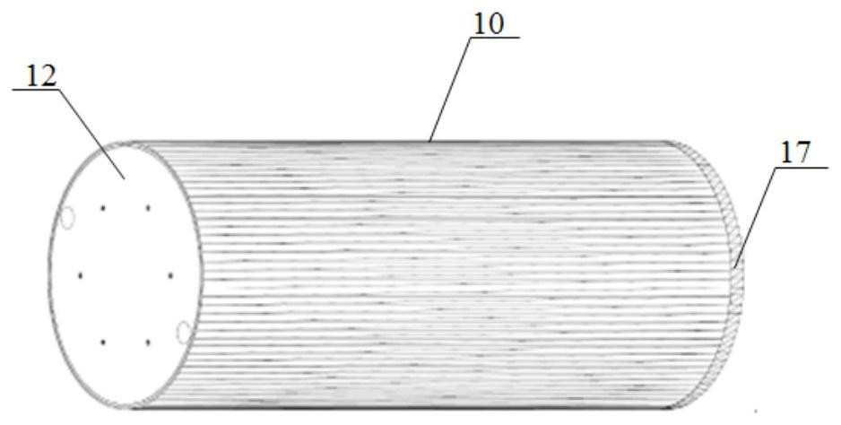
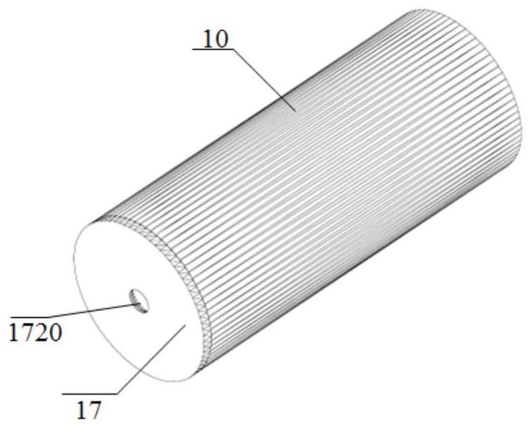
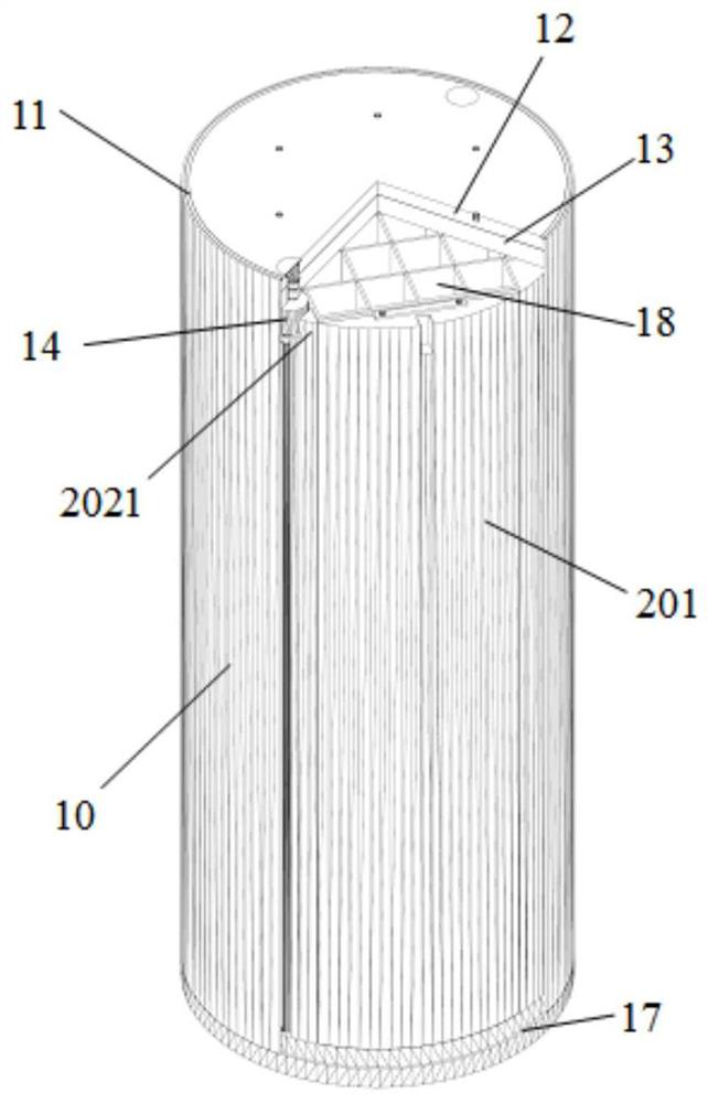
[0084] See Figure 1 to Figure 27 As shown, the spent fuel storage tank of the nuclear power plant of the present invention includes:

[0085] Cylinder 10;

[0086] The top cover 12 is fixedly connected to the top of the cylinder 10, and the top cover 12 is provided with a first drainage hole 122 and a first inflation hole 123 penetrating therethrough;

[0087] The shielding cover 13 is arranged inside the cylinder 10 and corresponding to the top cover 10. The shielding cover 13 is provided with a second drainage hole 132 corresponding to the position of the first d...


PUM


Abstract

The invention discloses a spent fuel storage tank for a nuclear power plant. The spent fuel storage tank comprises a cylinder, a top cap which is fixedly connected with the top of the cylinder and isprovided with a first draining hole and a first inflating hole in a running through manner, a shielding cover plate which is arranged inside the cylinder and is arranged corresponding to the top cap,a bottom plate which is fixed at the bottom of the cylinder, a fuel grid which is arranged in the cylinder and put on the bottom plate, and a heat-conductive metal block which is arranged between theinner wall of the cylinder and the fuel grid, wherein a second draining hole runs through the shielding cover plate, and is arranged corresponding to the position of the first draining hole, a secondinflating hole is formed corresponding to the first inflating hole in a running through manner; draining components are inserted in the first and second draining holes in an embedded manner; inflatingcomponents are inserted in the first and second inflating holes in an embedded manner; and the draining components and the inflating components are fixed on the inner surface of the cylinder. Compared with the prior art, the spent fuel storage tank has the advantages that the cover plate is convenient in assembly positioning, solder sealing and cut retrieving operations and is simple in processing manufacture, and horizontal storage and vertical storage are available.

Description

Technical field [0001] The invention belongs to the field of nuclear power. More specifically, the invention relates to a spent fuel storage tank for a nuclear power plant. Background technique [0002] The spent fuel storage tank is a device for loading and storing spent fuel, which can meet the long-term storage of spent fuel components in nuclear power plants. [0003] The spent fuel storage tanks of nuclear power plants in the prior art are mainly horizontal concrete storage tanks. Although the spent fuel assembly loading function can be realized, the convenience and safety of equipment operation and operation (radiation protection), as well as equipment manufacturing and equipment There are still some problems in storage, mainly reflected in: [0004] (1) Difficulty in underwater installation and positioning of horizontal spent fuel storage tank cover [0005] The existing horizontal spent fuel storage tank cover plate includes a shielding cover plate, an inner layer and an oute...

Claims


Application Information

Patent Timeline
Patent Type & Authority Patents(China)
IPC IPC(8): G21C19/06G21C19/04
CPCG21C19/04G21C19/06Y02E30/30
Inventor 程呈张学岭唐琼辉杨寿海徐晓莫怀森
Owner CHINA NUCLEAR POWER DESIGN COMPANY
Why Eureka
Try Eureka