
Sparse array MIMO antenna

A sparse array and antenna technology, applied in the field of sparse array MIMO antennas, can solve the problems of no antenna layout optimization and high side lobes, and achieve the effect of improving performance and avoiding side lobes.

Active Publication Date: 2019-04-09
福瑞泰克智能系统有限公司
View PDF5 Cites 5 Cited by
  • Summary
  • Abstract
  • Description
  • Claims
  • Application Information

AI Technical Summary

Problems solved by technology

[0005] Among the existing automotive millimeter-wave radars, a small number of radars use sparse arrays, but the side lobes are high, and the antenna arrays are not optimized.

Method used


Image

  • Sparse array MIMO antenna
  • Sparse array MIMO antenna
  • Sparse array MIMO antenna

Examples


Embodiment 1

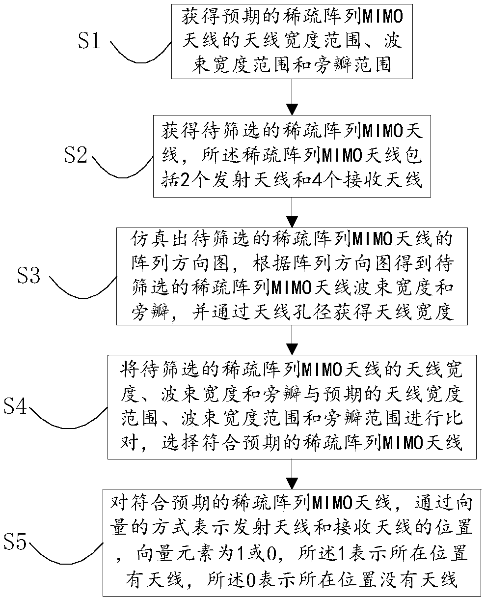
[0048] An embodiment of the present invention provides a method for obtaining a sparse array MIMO antenna, such as figure 1 As shown, the method includes:

[0049] S1. Obtain the antenna width range, beam width range and side lobe range of the expected sparse array MIMO antenna;

[0050] S2. Obtain the sparse array MIMO antenna to be screened, the sparse array MIMO antenna includes 2 transmitting antennas and 4 receiving antennas;

[0051] S3. Simulate the array pattern of the sparse array MIMO antenna to be screened, obtain the beamwidth and sidelobe of the sparse array MIMO antenna to be screened according to the array pattern, and obtain the antenna width through the antenna aperture;

[0052] S4. Compare the antenna width, beam width and side lobe of the sparse array MIMO antenna to be screened with the expected antenna width range, beam width range and side lobe range, and select the expected sparse array MIMO antenna;

[0053] S5. Represent the positions of the transmi...

Embodiment 2

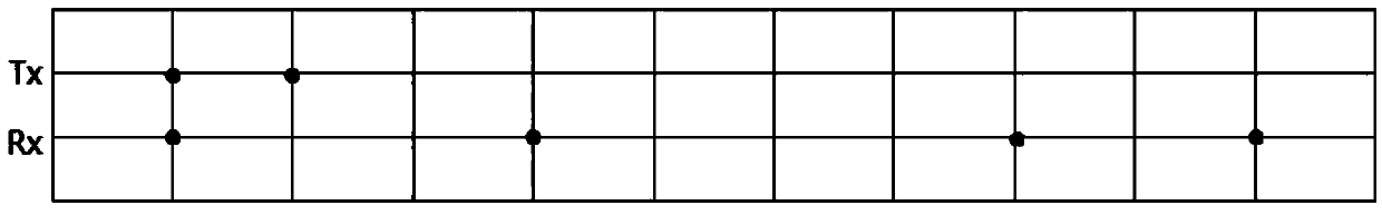
[0058] An embodiment of the present invention provides an 11-element sparse array MIMO antenna, and the 11-element sparse array MIMO antenna is used for a vehicle-mounted millimeter-wave radar.

[0059] The 11-element sparse array MIMO antenna described in the embodiment of the present invention includes 6 unidirectional antennas, wherein the transmitting antenna Tx group includes two antennas, and the receiving antenna Rx group includes four antennas. The position of the transmitting antenna and the receiving antenna is represented by a vector, and the vector elements are 1 or 0, 1 indicates that there is an antenna on the position, 0 indicates that there is no antenna on the position, and the distance between adjacent elements is equal.

[0060] Such as figure 2 As shown, in the 11-element sparse array MIMO antenna: Tx=[1 1], Rx=[1 0 0 1 00 0 1 0 1]. Communication quality can be improved by using MIMO (Multiple Input Multiple Output technology). The equivalent array of th...

Embodiment 3

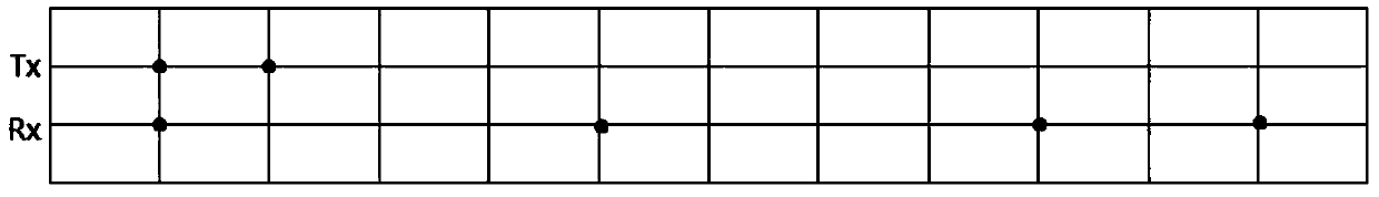
[0063] An embodiment of the present invention provides a 12-element sparse array MIMO antenna, and the 12-element sparse array MIMO antenna is used for a vehicle-mounted millimeter-wave radar.

[0064] The 12-element sparse array MIMO antenna described in the embodiment of the present invention includes 6 unidirectional antennas, wherein the transmitting antenna Tx group includes two antennas, and the receiving antenna Rx group includes four antennas. The position of the transmitting antenna and the receiving antenna is represented by a vector, and the vector elements are 1 or 0, 1 indicates that there is an antenna on the position, 0 indicates that there is no antenna on the position, and the distance between adjacent elements is equal.

[0065] Such as image 3 As shown, in the sparse array MIMO antenna with 12 elements: Tx=[1 1], Rx=[1 0 0 0 10 0 0 1 0 1], after MIMO (multiple input multiple output technology) The equivalent array of a 12-element sparse array MIMO antenna ...


PUM


Abstract

The invention relates to the field of an antenna, and provides a sparse array MIMO antenna. The sparse array MIMO antenna comprises two emission antennas and four receiving antennas, wherein the distance between the emission antennas is integral multiples of d; the distance among the receiving antennas is integral multiples of the d; the d is an integer being greater than 0; the emission waveformsbetween the emission antennas are orthorhombic; the space between the two emission antennas is Md; the M is a positive integer being greater than or equal to 1; the space between at least one group of adjacent receiving antennas in the four receiving antennas is greater than 2d; the positions of the emission antennas and the receiving antennas are expressed in a vector quantity mode; the vector quantity element is 1 or 0; the 1 shows that an antenna exists in the located position; and the 0 shows that no antenna exists in the located position. The sparse array MIMO antenna provided by the invention has the advantages that the angular resolution of the sparse array MIMO antenna is high; the side lobe is low relative to an ordinary sparse array; and the performance of vehicle-mounted millimeter-wave radar is improved.

Description

technical field [0001] The invention relates to the field of antennas, in particular to a sparse array MIMO antenna. Background technique [0002] The intelligent driving system is a comprehensive system that integrates functions such as advanced information control technology, scenario environment perception, and multi-level assisted driving. The intelligent driving system can assist the driver in driving, and the driver can respond to the actual road conditions under a series of prompts from the intelligent system. [0003] In the intelligent driving system, it is necessary to collect information about the external environment and driver behavior. In the collection of the surrounding environment, model building, and obstacle detection, millimeter-wave radar plays an important role, and has been widely used in scenarios such as automatic parking and adaptive cruise. With the rapid development of intelligent driving, millimeter-wave radar has become the main sensor of ADAS...

Claims


Application Information

Patent Timeline
IPC IPC(8): H01Q21/28H01Q21/00H01Q1/32
CPCH01Q1/3233H01Q21/00H01Q21/28
Inventor 颜福才
Owner 福瑞泰克智能系统有限公司
Features
  • Generate Ideas
  • Intellectual Property
  • Life Sciences
  • Materials
  • Tech Scout
  • Unparalleled Data Quality
  • Higher Quality Content
  • 60% Fewer Hallucinations
Learn More