Projector image distortion correction method and device and medium

An image distortion and projector technology, applied in the field of computer-readable storage medium and projector image distortion correction, can solve the problems of low correction efficiency, long correction time, projection pattern distortion, etc., so as to improve the correction efficiency and shorten the correction time. Effect

Inactive Publication Date: 2019-04-09
GOERTEK OPTICAL TECH CO LTD
View PDF6 Cites 2 Cited by
  • Summary
  • Abstract
  • Description
  • Claims
  • Application Information

AI Technical Summary

Problems solved by technology

Due to the technological characteristics of the laser beam scanning projector, the output projection graphics will be distorted
[0004] In the prior art, the distorted image is generally corrected by manual correction, which leads to long correction time and low correction efficiency

Method used


Image

  • Projector image distortion correction method and device and medium
  • Projector image distortion correction method and device and medium
  • Projector image distortion correction method and device and medium

Examples


Embodiment Construction

[0044] It should be understood that the specific embodiments described here are only used to explain the present invention, not to limit the present invention.

[0045] The main solution of the embodiment of the present invention is:

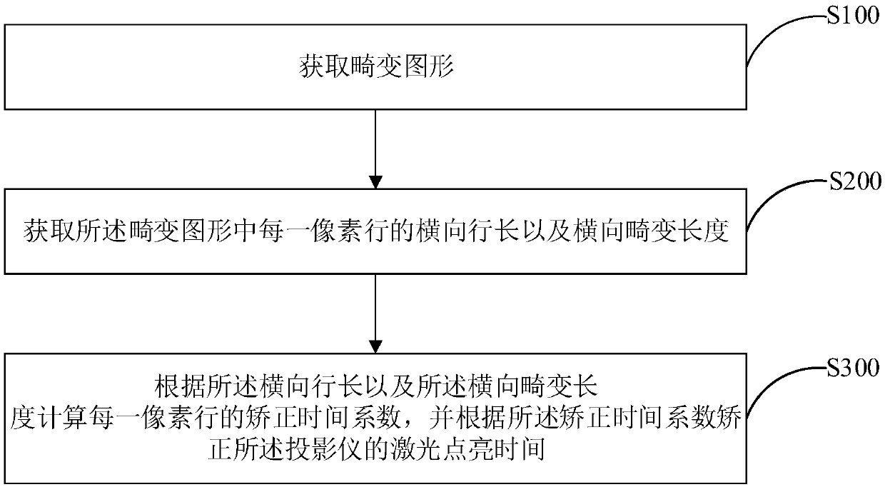
[0046] Get the distorted graphics;

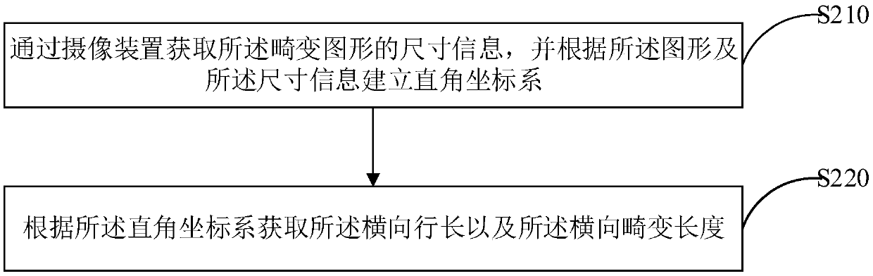
[0047] Acquiring the horizontal row length and the horizontal distortion length of each pixel row in the distorted pattern;

[0048] Calculating a correction time coefficient of each pixel row according to the horizontal row length and the horizontal distortion length, and correcting the laser light-on time of the projector according to the correction time coefficient.

[0049] A method, device, and computer-readable storage medium for correcting image distortion of a projector proposed by an embodiment of the present invention obtain a distorted image, and then obtain the horizontal line length and lateral distortion length of each pixel row in the distorted image, and then according to the The horizontal ...


PUM


Abstract

The invention discloses a projector image distortion correction method. The method comprises the following steps: obtaining a distorted image; o btaining a transverse row length and a transverse distortion length of each pixel row in the distorted image; and calculating a correction time coefficient of each pixel row according to the transverse row length and the transverse distortion length, andcorrecting the laser lighting time of the projector according to the correction time coefficient. The invention also discloses a projector image distortion correction device and a computer readable storage medium. The invention provides the projector image distortion correction method, and solves the technical problems of long correction time and low correction efficiency of a distorted image in the prior art.

Description

technical field [0001] The invention relates to the field of miniature projection technology, in particular to a correction method and device for image distortion of a projector and a computer-readable storage medium. Background technique [0002] The laser beam scanning projector has the advantages of simple structure, small size, small optical path loss, low power consumption, wide color range, high contrast, high resolution, and no need for focusing. [0003] The laser beam scanning projector uses its main component MEMS (Micro-Electro-Mechanical System, Micro-Electro-Mechanical System) to control the mirror to swing around the horizontal and vertical axes to realize the scanning of the laser beam. In the MEMS driving signal, the horizontal direction is driven by a sinusoidal signal consistent with the horizontal resonance frequency of the MEMS, and the vertical direction is driven by a 60 Hz sawtooth wave. Due to the technological characteristics of the laser beam scann...

Claims


Application Information

Patent Timeline
Patent Type & Authority Applications(China)
IPC IPC(8): H04N9/31
CPCH04N9/3155H04N9/3161H04N9/3185
Inventor 高文刚
Owner GOERTEK OPTICAL TECH CO LTD
Why Eureka
Try Eureka