Charging device of electric automobile and operating method thereof

A charging device and technology for electric vehicles, applied in electric vehicle charging technology, electric vehicles, charging stations, etc., can solve problems affecting charging safety, charging plug damage, charging devices that cannot detect charging dynamics at the user's time, and achieve intelligentization Operation, ensuring safety, and facilitating rational use of time

Pending Publication Date: 2019-04-12
张录
View PDF7 Cites 4 Cited by
  • Summary
  • Abstract
  • Description
  • Claims
  • Application Information

AI Technical Summary

Problems solved by technology

[0004] The purpose of the present invention is to provide a charging device for electric vehicles and its working method to solve the problems that the existing charging device for electric vehicles is likely to cause damage to the charging plug and affect charging safety and that the charging device cannot allow users to detect charging dynamics in real time

Method used


Image

  • Charging device of electric automobile and operating method thereof
  • Charging device of electric automobile and operating method thereof
  • Charging device of electric automobile and operating method thereof

Examples


Embodiment 1

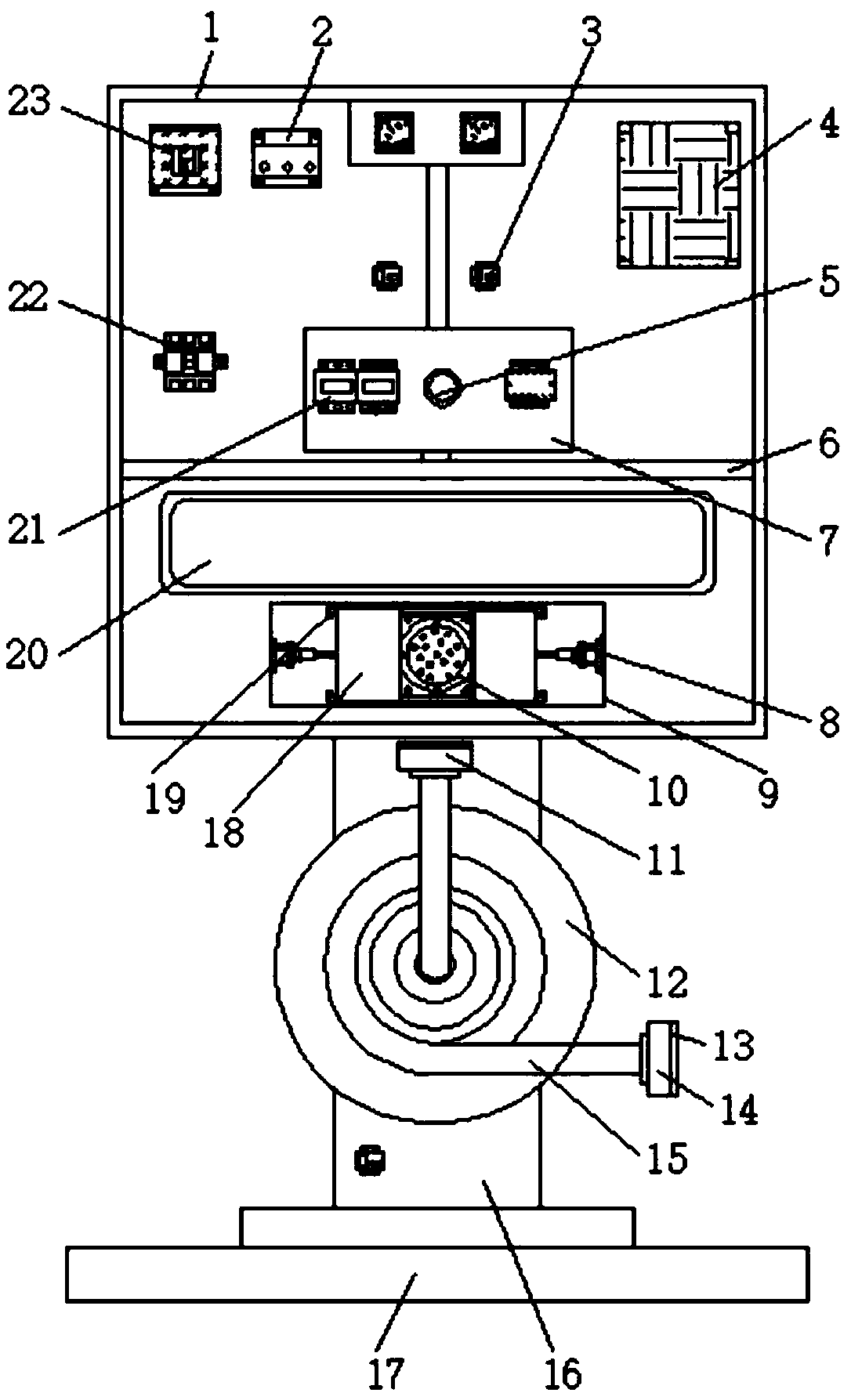
[0035] see Figure 1-Figure 8As shown, the present invention provides the following technical solutions: a charging device for electric vehicles, including a support column 16, the top of the support column 16 is fixedly connected with a fuselage 1 by bolts, and the inside of the fuselage 1 is provided with a processor 2 and a controller 23. It is convenient to carry out information processing and internal device control on the charging device, so as to realize intelligence. The processor 2 is located on one side of the controller 23, and a panel 7 is arranged on the outer wall of one side of the support column 16, and the panel 7 is far away from the body 1. A power switch 5 and a leakage protection switch 21 are embedded on one side of the outer wall, which play the role of leakage protection to ensure that the circuit can be cut off in case of leakage to protect the charging device and the car. The power switch 5 is located on one side of the leakage protection switch 21. A...

Embodiment 2

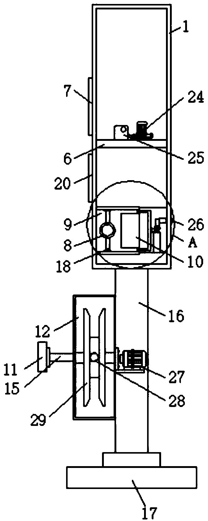
[0045] Please refer to Figure 1-Figure 8 As shown, after the charging is completed, when the first plug 11 is pulled out from the socket 10, the pressure received by the second pressure sensor 32 changes from presence to absence, and the controller 23 controls the change of the pressure information on the second pressure sensor 32. 23 controls the work of the hydraulic pump 24, the hydraulic pump 24 presses the hydraulic oil in the hydraulic oil tank 25 into the hydraulic cylinder 8, the hydraulic cylinder 8 pushes the cover plate 18 to move on the chute 33 through the hydraulic rod, and the two cover plates 18 move the inner cavity The space of the socket 10 in 9 is closed, the controller 23 controls the fan 27 to work, the fan 27 draws the air near the socket 10 into the one-way pipe 36, the air pressure on one side of the one-way pipe 36 increases, and the air pressure pushes the baffle 38 moves, and the second spring 39 stretches, and the air passes through the gap betwee...

Embodiment 3

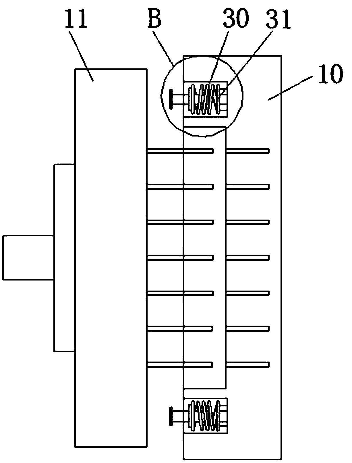
[0047] Please refer to Figure 1-Figure 8 As shown, after the first plug 11 and the second plug 14 are pulled out from the socket 10 and the automobile respectively, the controller 23 controls the motor 23 to rotate, and the motor 23 drives the winding wheel 29 to rotate through the rotating shaft, and the second plug 14 is connected A part of the transmission cable cover 15 is wound on the take-up wheel 29 under the rotation of the take-up wheel 29 and stored in the protective cover 12, and a part of the transmission cable cover 15 connected to the first plug 11 is rotated under the condition of the take-up wheel 29 Rotate to ensure that the second plug 14 can be accommodated, and the double-plug design of the first plug 11 and the second plug 14 can ensure that the socket 10 is in a protected state, avoiding the connection between the charging device and the transmission cable sleeve 15 under the influence of external factors The problem of falling off and damage at the plac...


PUM


Abstract

The invention discloses a charging device of an electric automobile and an operating method thereof. The charging device comprises a supporting column, wherein the top of the supporting column is fixedly connected with a machine body through bolts; a processor and a controller are arranged inside the machine body; the processor is positioned on one side of the controller; a panel is arranged on the outer wall of one side of the supporting column; a power switch and an electric leakage protection switch are embedded in the outer wall of the side, far away from the machine body, of the panel; the power switch is positioned on one side of the electric leakage protection switch. According to the charging device, a socket can be sealed inside the charging device through a movable cover plate, the problem that the socket is exposed outside to be easily affected by dust and rainwater is avoided, the problem that the socket is damaged under the influence of external factors is further avoided,air inside the accessories of the socket can be pumped away through a draught fan and a single-way tube, and the problem that electrical components are affected by damp and damaged to trigger safetyaccidents because rainwater inside air permeates into the charging device through the socket is avoided effectively in a formed vacuum environment.

Description

technical field [0001] The invention belongs to the technical field of charging devices for electric vehicles, and in particular relates to a charging device for electric vehicles and a working method thereof. Background technique [0002] With the upgrading of the concept of environmental protection, traditional gasoline and diesel powered vehicles are difficult to be respected today and in the future. The environmental protection of electric energy makes it applied to vehicles, thus giving birth to electric vehicles, which are powered by on-board power supplies. Motors are used to drive the wheels, and electric vehicles are mostly charged by charging piles and charging stations. [0003] However, most of the existing electric vehicle charging devices use plugs and car sockets for charging, which will easily cause the connecting cable between the charging device and the plug to be dragged for a long time to cause shedding and wear, and the plug will be easily damaged for a ...

Claims


Application Information

Patent Timeline
Patent Type & Authority Applications(China)
IPC IPC(8): B60L53/31B60L53/30B60L53/16B60L53/68
CPCY02T90/16Y02T10/7072Y02T10/70Y02T90/14Y02T90/12
Inventor 张录
Owner 张录
Why Eureka
Try Eureka