Die fixing mechanism of pressing machine

A technology of fixing mechanism and pressing machine, which is applied in blowing glass forming machine, glass production, etc. It can solve the problems of low efficiency and unqualified prototype, and achieve the effects of easy demoulding, improved pressing quality, and uniform force

Inactive Publication Date: 2019-04-12
CHONGQING XINGBAOXING GLASS PROD CO LTD
View PDF0 Cites 0 Cited by
  • Summary
  • Abstract
  • Description
  • Claims
  • Application Information

AI Technical Summary

Problems solved by technology

[0003] The present invention intends to provide a pressing machine mold fixing mechanism to solve the problems of low efficiency and unqualified pressed prototype when the existing pressing machine mold is fixed by manual clamping

Method used


Image

  • Die fixing mechanism of pressing machine
  • Die fixing mechanism of pressing machine
  • Die fixing mechanism of pressing machine

Examples


Embodiment 1

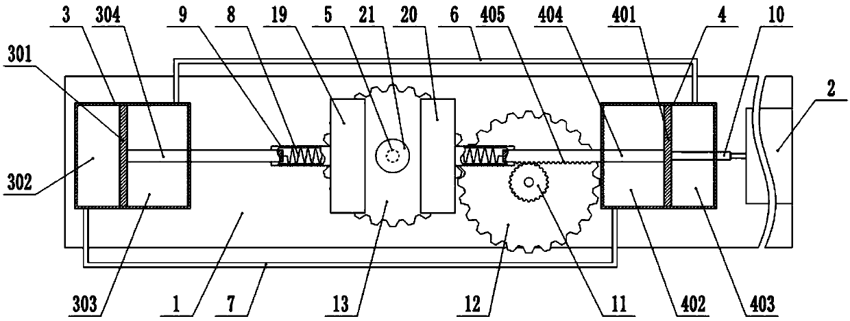
[0027] The embodiment is basically as figure 1 Shown: the mold fixing mechanism of the pressing machine, including the workbench 1, the cylinder 2 and the first cylinder 3 and the second cylinder 4 arranged beside the mold, the mold includes a left movable mold 19, a right movable mold 20 and a bottom mold 21, Form cavity when left movable mold 19, right movable mold 20 and bottom mold 21 close molds. The workbench 1 is rotatably connected with a vertically arranged first rotating shaft 5 , and the top end of the first rotating shaft 5 is fixedly connected with the bottom mold 21 . The first cylinder body 3 is arranged on the left side of the left movable mold 19 , and the second cylinder body 4 is arranged on the right side of the right movable mold 20 .

[0028] The first cylinder 3 and the second cylinder 4 are respectively slidingly connected with a first piston 301 and a second piston 401, and the first piston 301 divides the first cylinder 3 into an independent first ch...

Embodiment 2

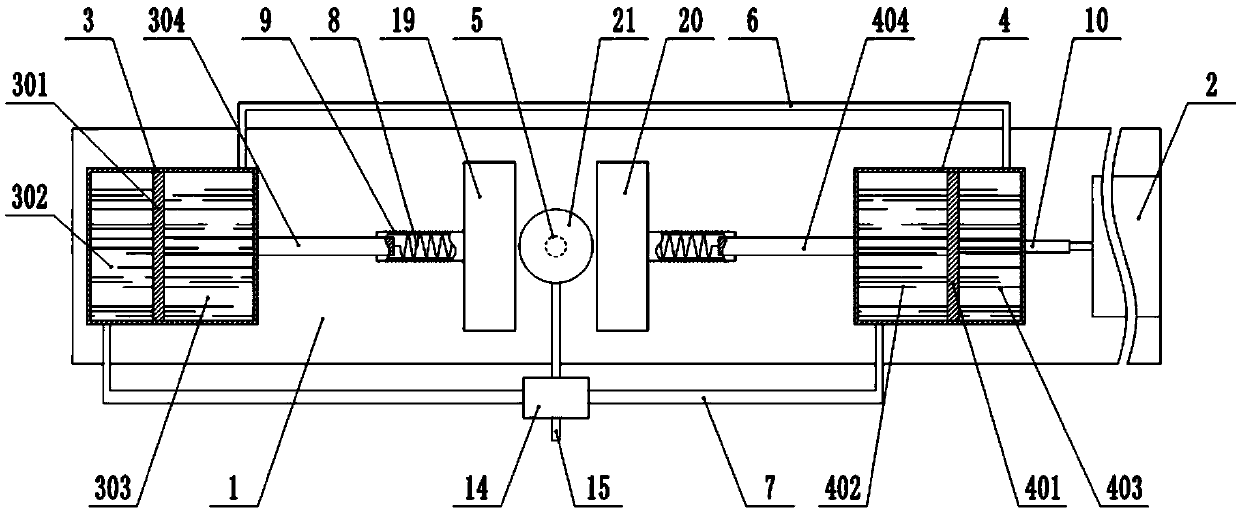
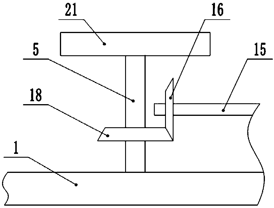
[0038] This embodiment differs from Embodiment 1 in that: figure 2 , image 3 and Figure 4 As shown, the first chamber 302, the second chamber 303, the third chamber 402 and the fourth chamber 403 are all filled with liquid, and in this embodiment, the liquid is tap water. The middle part of the second pipeline 7 communicates with a drive chamber 14, and the drive chamber 14 is rotatably connected with a second rotating shaft 15 arranged horizontally. The second rotating shaft 15 is coaxially fixed with a first bevel gear 16 and a plurality of toggle plates 17. 5. The second bevel gear 18 is fixedly installed coaxially, and the second bevel gear 18 meshes with the first bevel gear 16. The toggle plate 17 is located in the driving cavity 14, and the lower end of the toggle plate 17 extends into the second bevel gear when rotating. Inside the pipeline 7.

[0039] During specific implementation, when the telescopic end of the cylinder 2 drives the push rod 10 to move to the ...


PUM


Abstract

The invention relates to the technical field of glass forming, in particular to a die fixing mechanism of a pressing machine, which comprises a first cylinder body and second cylinder body which are arranged beside a die, wherein the die comprises a left moving die, a right moving die and a bottom die, the first cylinder body and the second cylinder body are respectively connected with a first piston and a second piston in a sliding manner, the first piston divides the first cylinder body into an independent first chamber and an independent second chamber, the second piston divides the secondcylinder body into a third chamber and a fourth chamber, and the second chamber is communicated with the fourth chamber; the first piston and the second piston are respectively and fixedly connected with a first piston rod and a second piston rod, the ends of the first piston rod and second piston rod are both fixedly connected with a spring, and the spring is respectively and fixedly connected with the left moving die and the right moving die; the mechanism also comprises a cylinder, a telescopic end of the cylinder is fixedly connected with a push rod which is fixedly connected with the first piston or the second piston. According to the invention, a blank body of a glass bottle can pressed by replacing manual pressing, and the production efficiency and production quality of the glass bottle are improved.

Description

technical field [0001] The invention relates to the technical field of glass forming, and specifically discloses a mold fixing mechanism for a pressing machine. Background technique [0002] Glass bottles, such as glass wine bottles, glass beverage bottles, etc., usually use a prototype molding machine (press machine) to pre-press the molten glass material into a prototype, and then place the prototype into a molding mold blowing machine to blow it into shape . The pressing machine usually includes two movable molds, and the outer wall of the movable mold is fixedly connected with the pressing rod. The staff applies pressure to the pressing rod to make the two movable molds fit together to form a mold cavity, so that the molten glass in the mold cavity The material is pressed into a prototype. However, the use of such a pressing method not only has the problem of high labor intensity of the staff, but also has the problems of limited production quantity of glass bottles an...

Claims


Application Information

Patent Timeline
Patent Type & Authority Applications(China)
IPC IPC(8): C03B9/193
CPCC03B9/193Y02P40/57
Inventor 刘德燕
Owner CHONGQING XINGBAOXING GLASS PROD CO LTD
Why Eureka
Try Eureka