Roof hydraulic fracturing multi-parameter integrated monitoring system and fracturing effect determination method
A technology for hydraulic fracturing and comprehensive monitoring, which is used in earth-moving drilling, gas discharge, safety devices, etc., which can solve the problem of crack propagation, the difficulty of obtaining pressure parameters of stress transfer law, and the inability to carry out the evaluation of the pressure relief effect of roof hydraulic fracturing. , the blind gun is difficult to deal with, etc., to achieve the effect of preventing and controlling the dynamic disaster of the rock burst roof, optimizing the construction process and optimizing the construction parameters
- Summary
- Abstract
- Description
- Claims
- Application Information
AI Technical Summary
Problems solved by technology
Method used
Image

Examples
Embodiment 1
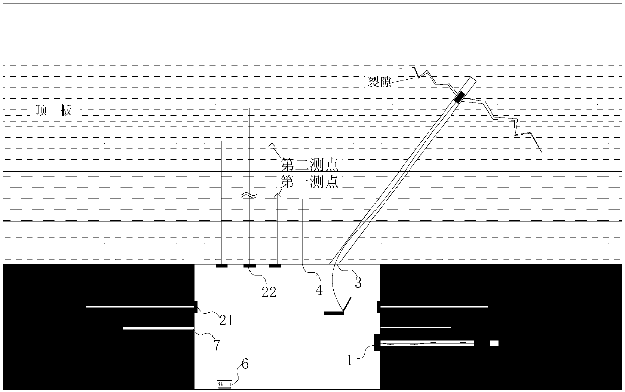
[0036] A roof hydraulic fracturing multi-parameter comprehensive monitoring system, such as figure 1As shown, the monitoring equipment of the system may include a borehole stress gauge 1, a bolt dynamometer 21, an anchor cable dynamometer 22, a borehole peeping instrument 3, a roof monitor 4, a support resistance measuring station 5, and a microseismic measuring station 6 and the surrounding rock deformation measuring station 7, it is also possible to select a borehole peeping instrument and more than two other combined monitoring equipment for comprehensive monitoring according to the actual situation on site. Borehole stress gauge 1 is set in the recovery roadway, and the borehole stress gauge 1 is set in the range of 20-30m on both sides of the hydraulic fracturing hole, which is used to monitor the surrounding rock of the mining roadway in the hydraulic fracturing area and the non-hydraulic fracturing area. Stress magnitude and stress concentration state. Anchor bolt and ...
Embodiment 2
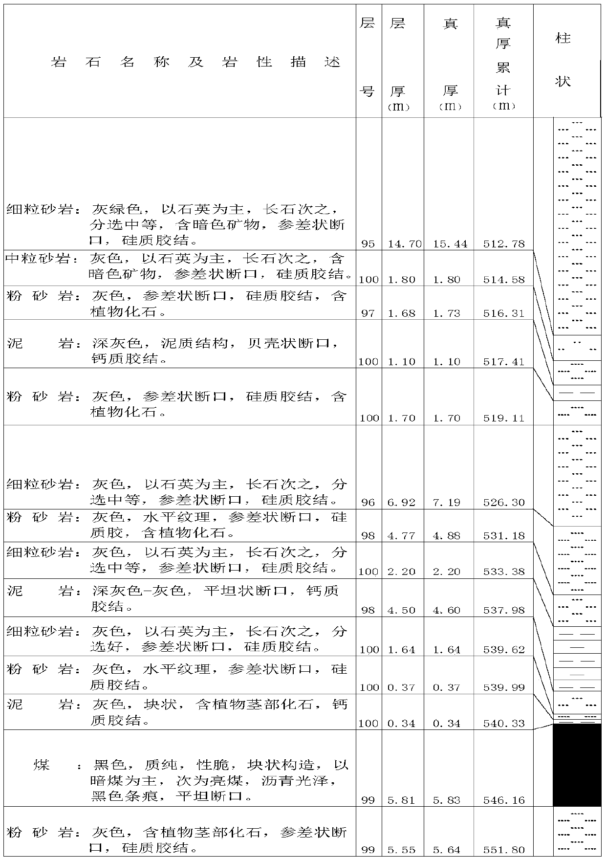
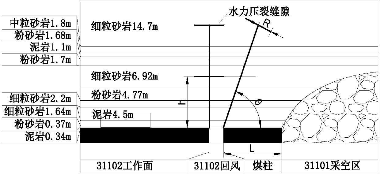
[0049] In order to further illustrate the roof hydraulic fracturing multi-parameter comprehensive monitoring system and the fracturing effect discrimination method proposed by the present invention, taking the 31101 working face, 31102 working face and 31103 working face of a certain mine as examples, the technical solution of the present invention is further described illustrate. The 31102 working face of this mine is located in the 3-1 coal seam, which is the second working face of this mining area. The east side of the working face is the 31101 working face, and the right side is the 31103 working face. Among them, the 31101 working face has been pushed and mined, and the return air trough of the 31102 working face is affected by the suspended roof of the 31101 working face, causing large deformation and serious bottom drum; and the 31102 working face’s auxiliary transportation trough will be used as the 31103 working face’s return air trough in the later stage , the coal ...
PUM
 Abstract
Description
Claims
Application Information
 - R&D
- Intellectual Property
- Life Sciences
- Materials
- Tech Scout
- Unparalleled Data Quality
- Higher Quality Content
- 60% Fewer Hallucinations
Browse by: Latest US Patents, China's latest patents, Technical Efficacy Thesaurus, Application Domain, Technology Topic, Popular Technical Reports.
© 2025 PatSnap. All rights reserved.Legal|Privacy policy|Modern Slavery Act Transparency Statement|Sitemap|About US| Contact US: help@patsnap.com