Portable strong electromagnetic environment simulation test platform and test method

A technology of environmental simulation and test platform, applied in the direction of measuring electricity, measuring devices, measuring electrical variables, etc., can solve the problems of time-consuming mechanical stirring reverberation chamber test, large rotational inertia of the stirrer, inability to disassemble and move, etc. The electromagnetic environment is real and effective, the available test space is increased, and the test time is saved

Pending Publication Date: 2019-04-12
ARMY ENG UNIV OF PLA
View PDF7 Cites 5 Cited by
  • Summary
  • Abstract
  • Description
  • Claims
  • Application Information

AI Technical Summary

Problems solved by technology

[0004] In the process of researching and using the reverberation chamber, we found that there are some deficiencies in the mechanically stirred reverberation chamber: First, the mechanical stirring device is installed inside the reverberation chamber, which reduces the available test space. If the mixer is placed for a long time, it will be deformed due to gravity. When the vertically installed mechanical stirrer is stepping and rotating, it cannot stop quickly and stably due to the large rotational inertia of the stirrer, which leads to a long time-consuming test of the mechanically stirred reverberation chamber. The second is mechanical stirring. The cost of the traditional reverberation chamber is expensive. For example, a reverberation chamber with a geometric size of 10.5m×8m×4.3m needs at least 3 million yuan only to build the shell; third, after the mechanically stirred reverberation chamber is built, it cannot be disassembled or moved. , it is necessary to dismantle and transport the tested equipment to relevant units with mechanically stirred reverberation chambers for experiments, which is not conducive to on-site testing. The existence of these problems affects the promotion and use of mechanically stirred reverberation chambers

Method used


Image

  • Portable strong electromagnetic environment simulation test platform and test method
  • Portable strong electromagnetic environment simulation test platform and test method
  • Portable strong electromagnetic environment simulation test platform and test method

Examples


Embodiment Construction

[0029] The technical solutions in the embodiments of the present invention are clearly and completely described below in conjunction with the accompanying drawings in the embodiments of the present invention. Obviously, the described embodiments are only part of the embodiments of the present invention, not all of them. Based on the embodiments of the present invention, all other embodiments obtained by persons of ordinary skill in the art without making creative efforts belong to the protection scope of the present invention.

[0030] In the following description, a lot of specific details are set forth in order to fully understand the present invention, but the present invention can also be implemented in other ways different from those described here, and those skilled in the art can do it without departing from the meaning of the present invention. By analogy, the present invention is therefore not limited to the specific examples disclosed below.

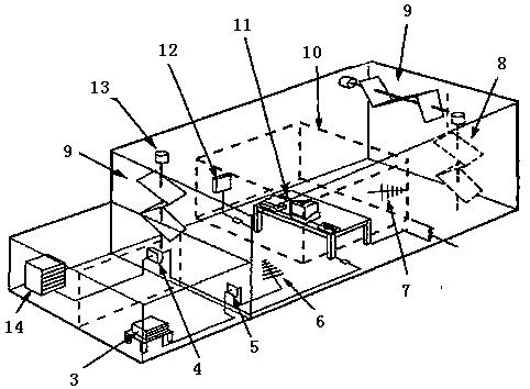
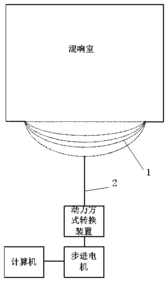
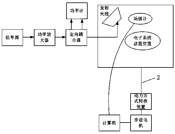
[0031] Such as Figure...


PUM


Abstract

The invention discloses a portable strong electromagnetic environment simulation test platform and a test method. The portable strong electromagnetic environment simulation test platform comprises a reverberation chamber, a signal transmitting device, and a shielding cloth drive device; the reverberation chamber comprises a three-dimensional frame structure connected by a dielectric rod and a shielding cloth covering the surface of the frame structure, the shielding cloth forms a fold structure on each wall surface of the three-dimensional frame structure, a transmitting antenna of the signaltransmitting device is located inside the reverberation room, and the signal transmitting device is used for transmitting test signals into the reverberation chamber through the transmitting antenna;and the power output end of the shielding cloth drive device is connected with a center point of the shielding cloth on a wall surface of the reverberation chamber to drive the shielding cloth to vibrate. The portable strong electromagnetic environment simulation test platform is easy to build, the cost is low, the lowest usable frequency can be lowered effectively, and the testing speed is high.

Description

technical field [0001] The invention relates to the technical field of measuring devices and methods for electromagnetic compatibility of electronic systems, in particular to a portable strong electromagnetic environment simulation test platform and a test method. Background technique [0002] With the improvement of electronic system integration, the electromagnetic compatibility (Electromagnetic Compatibility, EMC) problem between equipment and equipment, equipment and system, and system and system has become increasingly prominent, which greatly affects the performance of electronic systems or equipment. Experimental measurement is a key technical means to solve EMC problems, so a test platform that can quantitatively study EMC problems is a research hotspot. The Reverberation Chamber (Reverberation Chamber) is a new EMC test platform proposed after the Anechoic Chamber (Anechoic Chamber), Gigahertz TEM cell (GTEM), and Open Area Test Site (OATS). The commonly used mecha...

Claims


Application Information

Patent Timeline
Patent Type & Authority Applications(China)
IPC IPC(8): G01R31/00
CPCG01R31/001
Inventor 程二威陈亚洲周星赵敏王妍
Owner ARMY ENG UNIV OF PLA
Why Eureka
Try Eureka