LED (Light Emitting Diode) driving circuit based on power tube safety protection

A technology of LED drive and drive circuit, applied in the field of LED drive, can solve the problems of power tube burnout, lack of control of power tube drain current, rise of power tube drain current, etc., and achieve the effect of high stability

Pending Publication Date: 2019-04-12
GUANGDONG GDLED
View PDF0 Cites 1 Cited by
  • Summary
  • Abstract
  • Description
  • Claims
  • Application Information

AI Technical Summary

Problems solved by technology

[0003] In the prior art, LED drive circuits such as figure 1 As shown, when the rectified bus voltage or the drain voltage of the power tube is too high, the drain current of the power tube rises, resulting in exceeding the safe working range of the power tube and causing reliability problems
[0004] In the prior art, there is no control over the drain current of the power tube when the bus voltage or the drain voltage of the power tube is too high, and the phenomenon of power tube burning occurs frequently

Method used


Image

  • LED (Light Emitting Diode) driving circuit based on power tube safety protection
  • LED (Light Emitting Diode) driving circuit based on power tube safety protection
  • LED (Light Emitting Diode) driving circuit based on power tube safety protection

Examples


Embodiment 1

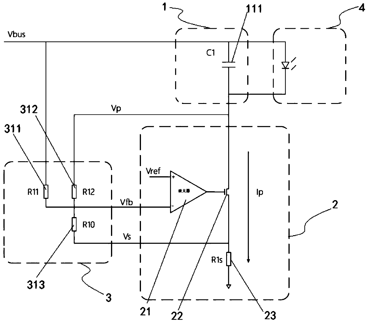
[0042]In one embodiment of the present invention, a LED drive circuit based on power tube safety protection is provided, such as image 3 As shown, the ripple suppression module 1 of the drive circuit includes a first capacitor 111, the positive pole of the first capacitor 111 is connected to the bus bar of the power distribution device, and the negative pole of the first capacitor 111 is connected to the input end of the power transistor 22, so The load 4 is connected in parallel to both ends of the first capacitor 111, and the first capacitor 111 suppresses the current ripple of the load module.

[0043] The control module 3 of the drive circuit includes a first resistor 311 (hereinafter referred to as R11), a second resistor 312 (hereinafter referred to as R12) and a third resistor 313 (hereinafter referred to as R10), and the first resistor 311 is set at between the bus bar of the power distribution device and the inverting input terminal of the amplifier 21; the second re...

Embodiment 2

[0049] In one embodiment of the present invention, a LED drive circuit based on power tube safety protection is provided, such as Figure 4 As shown, the ripple suppression module 1 of the drive circuit includes a first capacitor 111, the positive pole of the first capacitor 111 is connected to the bus bar of the power distribution device, and the negative pole of the first capacitor 111 is connected to the input end of the power transistor 22, so The load 4 is connected in parallel to both ends of the first capacitor 111, and the first capacitor 111 suppresses the current ripple of the load module.

[0050] The control module 3 of the drive circuit includes a first transconductance amplifier 321, a first constant current source 322, a grounding capacitor 323, a fourth resistor 324 (hereinafter referred to as R21) and a fifth resistor 325 (hereinafter referred to as R20), so The output end of the first constant current source 322, the output end of the first transconductance a...

Embodiment 3

[0058] In one embodiment of the present invention, a LED drive circuit based on power tube safety protection is provided, such as Figure 5 As shown, the ripple suppression module 1 of the driving circuit includes a second capacitor 121, a third capacitor 122, a voltage dividing resistor 123, a third constant current source 124, and a second power tube 125. The anode of the second capacitor 121 is connected to the The power distribution device is connected to the bus bar, the load 4 is connected in series with the voltage dividing resistor 123 and the third constant current source 124 to form a branch circuit, the branch circuit is connected in parallel with the second capacitor 121, and the third capacitor 122 is connected to the first Three constant current sources 124 are connected in parallel, and the drain and source of the second power transistor 125 are connected in parallel to the two ends of the voltage dividing resistor 123 and the third constant current source 124, a...


PUM


Abstract

The invention discloses an LED (Light Emitting Diode) driving circuit based on power tube safety protection. The circuit comprises a ripple wave inhibition module, a voltage and current conversion module and a control module, wherein the input end of the ripple wave inhibition module and one end of the control module are connected with the bus of a power distribution device; the ripple wave inhibition module is connected with a load in parallel; the voltage and current conversion module comprises an amplifier, a power tube and a sampling resistor, wherein the output end of the amplifier is connected with the grid electrode of the power tube; the output end of the ripple wave inhibition module is connected with the drain electrode of the power tube; the source electrode of the power tube issubjected to ground connection through the sampling resistor; the drain electrode and the source electrode of the power tube, the same-phase input end of the amplifier and / or the reverse phase inputend of the amplifier are independently connected with the control module; and the control module enables current which flows through the power tube to be lowered along with the rise of bus voltage. The control module is designed in the LED driving circuit, so that current which flows through the drain electrode lowers when power tube drain electrode voltage in the voltage and current conversion module rises so as to guarantee the safe working area of the power tube.

Description

technical field [0001] The invention relates to the field of LED driving, in particular to an LED driving circuit based on power tube safety protection. Background technique [0002] As an efficient new light source, LED is widely used in lighting in various fields due to its long life, low energy consumption, energy saving and environmental protection. In the LED driving circuit, the voltage-current conversion module composed of amplifier and power tube is the important core. [0003] In the prior art, LED drive circuits such as figure 1 As shown, when the rectified bus voltage or the drain voltage of the power tube is too high, the drain current of the power tube rises, resulting in exceeding the safe working range of the power tube and causing reliability problems. [0004] In the prior art, there is no control over the drain current of the power tube when the bus voltage or the drain voltage of the power tube is too high, and the phenomenon of burning out of the power ...

Claims


Application Information

Patent Timeline
IPC IPC(8): H05B33/08H05B44/00
CPCH05B45/50H05B45/00Y02B20/30
Inventor 陶冬毅刘明龙
Owner GUANGDONG GDLED
Why Eureka
Try Eureka