Plunger rotary-assembling machine

A screwing machine and plunger technology, applied in metal processing, metal processing equipment, manufacturing tools, etc., can solve the problems of speeding up the transfer efficiency of the plunger pump, uneven quality, low assembly efficiency, etc. Distribution efficiency, high assembly efficiency, and the effect of improving assembly efficiency

Inactive Publication Date: 2019-04-16
四川普什宁江机床有限公司
View PDF8 Cites 4 Cited by
  • Summary
  • Abstract
  • Description
  • Claims
  • Application Information

AI Technical Summary

Problems solved by technology

[0004] Aiming at the defects of low assembly efficiency, high difficulty and uneven quality in the prior art, the invention discloses a plunger screwing machine, which can not only greatly speed up the transfer efficiency of the plunger pump, but also assemble The quality is highly uniform, which greatly improves the quality of the plunger pump, reduces the difficulty of assembly and the labor intensity of workers

Method used


Image

  • Plunger rotary-assembling machine
  • Plunger rotary-assembling machine

Examples


Embodiment 1

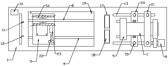
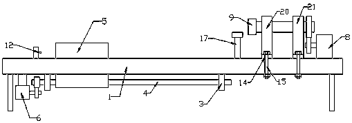
[0029] This embodiment, as the basic embodiment of the present invention, discloses a plunger screwing machine, the specific structure is as follows figure 1 As shown, it includes a frame 1, the frame 1, the frame 1 is fixedly provided with a slide bar 2, and at the same time, the frame 1 is also fixedly provided with a rolling bearing 3, and the rolling bearing 3 is fixedly provided with a transmission screw 4, and The transmission lead screw 4 is level with the slide bar 2, and the slide bar 2 is provided with a mobile workbench 5 slidingly through the linear motion bearing 17, and the mobile workbench 5 is connected with the drive lead screw 4 threaded at the same time; One end of the frame 1 is fixedly provided with a rotating motor 6, and the rotating motor 6 is connected to the transmission screw 4 through a transmission gear; the other end of the frame 1 is fixedly provided with a left support frame 20 and a right support frame 21, and the left support frame 20 and Roll...

Embodiment 2

[0031] This embodiment, as a preferred embodiment of the present invention, discloses a plunger screw, the specific structure is as follows figure 1 and figure 2 As shown, a stopper is arranged on the frame 1, and a speed sensor 11 and a distance sensor 12 are arranged on the stopper and the mobile workbench 5, and the speed sensor 11 and the distance sensor 12 are connected with the controller 10 respectively. The input end is connected, and the frame 1 is also provided with a travel switch 19 for limiting the range of movement of the mobile workbench, and the travel switch 19 is connected with the input end of the controller 10; the frame 1 is provided with a waist hole 13, The left support frame 20 and the right support frame 21 are all provided with the installation hole 14 that is adapted to the waist hole 13, and the installation hole 14 is provided with a frame for connecting the frame 1 with the left support frame 20 and the right support frame 21. fastening bolts 15...


PUM


Abstract

The invention discloses a plunger rotary-assembling machine. The plunger rotary-assembling machine comprises a machine frame. One end of the machine frame is slidably connected with a movable workbench through a sliding rod and a transmission lead screw. A supporting frame is fixedly arranged at the other end of the machine frame. A rotary shaft is rotatably arranged on the supporting frame through a rolling bearing. A chuck is arranged on the rotary shaft. The transmission lead screw and the rotary shaft are separately connected with a rotary motor and a servo motor. According to the plungerspin-assembling machine, a to-be-assembled cylinder body is fixed to the movable workbench, a plunger is mounted on the chuck, the chuck drives the plunger to rotate, the movable workbench drives theto-be-assembled cylinder body to move linearly, and then the plunger is rotatably assembled into the to-be-assembled cylinder body; and the assembling efficiency is high, the assembling difficulty isgreatly lowered, and the labor intensity of workers is relieved.

Description

technical field [0001] The invention relates to the technical field of general machinery, in particular to a plunger screwing machine. Background technique [0002] As the core component of the plunger pump, the plunger is slidingly assembled in the cylinder of the plunger pump. When the plunger is pulled back, the valve of the outlet pipe is closed and the valve of the inlet pipe is opened, and the fluid is sucked into the cylinder from the inlet pipe. In the process, when the plunger moves forward, the valve of the inlet pipe is closed and the valve of the outlet pipe is opened, the fluid in the cylinder is pressed and sent out from the outlet pipe, the plunger reciprocates continuously in the cylinder, and the fluid flows continuously. This is the function of the plunger. Generally, the plunger is mainly used in places with high working pressure, and other mechanisms are used in places with low pressure. Therefore, the assembly accuracy of the plunger has a great influenc...

Claims


Application Information

Patent Timeline
IPC IPC(8): B23P19/04B23P19/00
CPCB23P19/00B23P19/04
Inventor 李云江赵军罗兴征李波
Owner 四川普什宁江机床有限公司
Why Eureka
Try Eureka