Pipe processing equipment and technology

A technology for processing equipment and pipes, applied in the field of pipe processing equipment and processing technology, can solve the problems of low production efficiency and high labor costs, and achieve the effect of improving production efficiency and saving labor costs

Active Publication Date: 2019-04-16
上海天原集团胜德塑料有限公司
View PDF4 Cites 3 Cited by
  • Summary
  • Abstract
  • Description
  • Claims
  • Application Information

AI Technical Summary

Problems solved by technology

[0003] Aiming at the problems of low pipe production efficiency and high labor cost, the first technical purpose of the present invention is to provide a pipe processing equipment, which can realize automatic cutting and grooving of pipes by using a cutting device and a grooving device, thereby reducing labor costs and greatly Improve pipe production efficiency

Method used


Image

  • Pipe processing equipment and technology
  • Pipe processing equipment and technology
  • Pipe processing equipment and technology

Examples


Embodiment 1

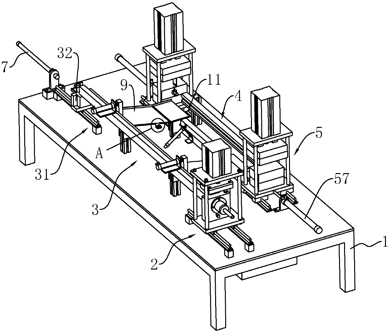
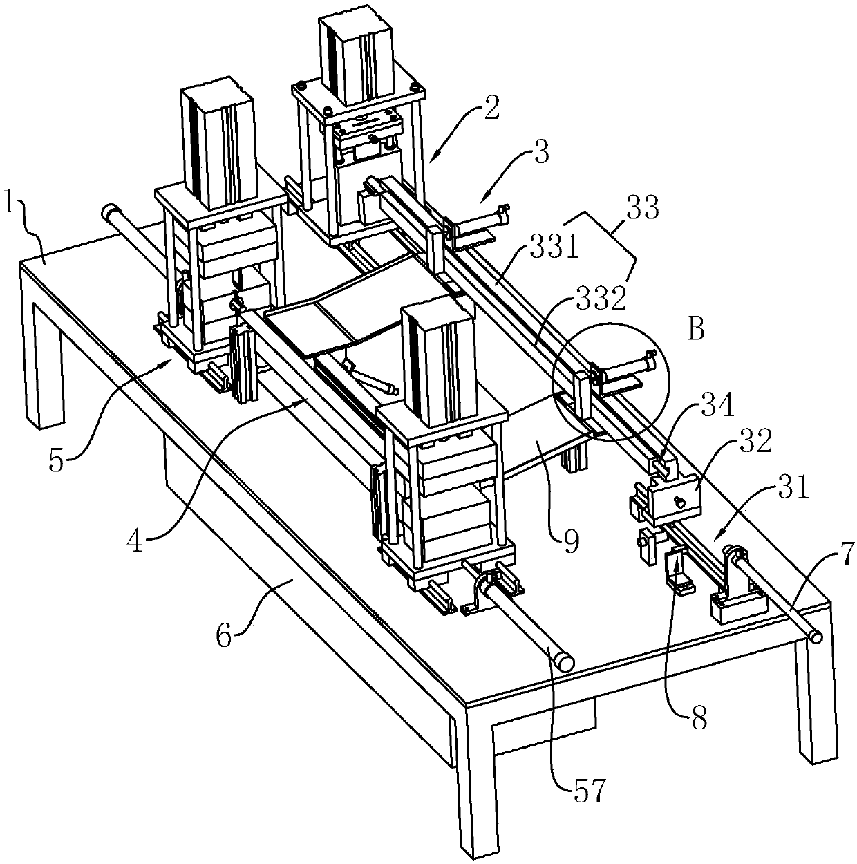
[0059] See attached figure 1 , A pipe processing equipment, which is integrally arranged on the side of the extruder where the pipe is extruded, and includes a frame 1, on which a cutting device is arranged on the side close to the extruder; at the same time, the side of the cutting device is also Equipped with slotting device. The cutting device includes a receiving assembly 3 for receiving the pipe and a cutting assembly 2 for cutting the pipe, and the grooving device includes a clamping assembly 4 for clamping the pipe and a grooving assembly 5 for grooving the pipe.

[0060] In actual work, the pipe is extruded by an extruder and enters the receiving assembly 3; after the pipe enters the receiving assembly 3, the pipe can continue to be fed, and then the cutting assembly 2 can cut the pipe. After the pipe is cut, the cut pipe can be clamped and fixed in the clamping assembly 4, and the slotting assembly 5 can punch out the required notches on the pipe according to the product...

Embodiment 2

[0080] See attached Picture 10 , A pipe processing technology, including the following steps:

[0081] S1. Extrusion: Use an extruder to extrude semi-finished pipes.

[0082] S2, primary cooling; a cooling water area is set at the end of the extruder, the semi-finished pipe will enter the cooling water area after the extrusion is completed, and the temperature of the cooling water used in the cooling water area is 50-70°C.

[0083] S3. Sizing; a sizing die is set at the end of the cooling water area, and a sizing area is formed in the sizing die. The internal temperature of the sizing area is 50-70℃; after the semi-finished pipe is extruded through the sizing die, the semi-finished product The diameter of the pipe is finally determined.

[0084] S4. Secondary cooling: A natural water cooling area is provided at the end of the sizing mold, and the temperature of the cooling water used in the natural water cooling area is 10-20°C.

[0085] S5. Cutting: After the pipe is cooled for the s...


PUM


Abstract

The invention discloses pipe processing equipment and technology, and relates to the technical field of pipe processing. The pipe processing equipment comprises a rack, a cutting-off device and a grooving device, the cutting-off device comprises a bearing assembly and a cutting-off assembly, and the grooving device comprises a clamping assembly and a grooving assembly; a bearing space is formed ina combined bearing component and further internally provided with a positioning piece; the cutting-off device comprises a cutting-off driving piece fixedly erected on the rack, and the cutting-off driving piece is connected with a first cutting knife; the clamping assembly comprises a fixed clamping piece and a movable clamping piece, and the rack is further provided with a clamping driving piece; and the grooving assembly comprises a grooving driving piece connected with a second cutting knife. According to the pipe processing equipment, the production cost is lowered advantageously, the pipe processing quality can be improved greatly, the pipe production efficiency can be greatly improved; and in addition, the invention further provides the pipe processing technology, the recycling property of pipes can be effectively lowered, and the use performance of the pipes is ensured.

Description

Technical field [0001] The invention relates to the technical field of pipe processing, in particular, it relates to a pipe processing equipment and processing technology. Background technique [0002] Plastic pipes are mostly used for injection molding with extruders and related supporting molds; in the actual production process, when the pipes are extruded by the extruder, in order to meet customer needs, manufacturers usually need to cut the pipes according to specific specifications and follow Customers need to machine specific notches on the pipe. At present, the slitting and grooving processes of pipes are mostly carried out separately from the extrusion molding of pipes, which cannot be processed in one time on the assembly line, which not only indirectly increases labor costs, but also greatly affects the production efficiency of pipes. In addition, plastic pipes generally have high shrinkage. When the ambient temperature exceeds 100°C, the pipes are prone to shrinkage, ...

Claims


Application Information

Patent Timeline
IPC IPC(8): B29C48/09B26D9/00B26D7/06B26D7/32
CPCB26D7/0641B26D7/32B26D9/00
Inventor 王恩洪李红叶李国锋刘恒华
Owner 上海天原集团胜德塑料有限公司
Why Eureka
Try Eureka