Garbage compression device

A technology of garbage compression and equipment, which is applied in the direction of garbage bins, garbage transmission, garbage collection, etc., and can solve problems such as short service life, lack of sterilization and classification treatment, and reduced compression efficiency.

Inactive Publication Date: 2019-04-16
刘盼盼
View PDF6 Cites 13 Cited by
  • Summary
  • Abstract
  • Description
  • Claims
  • Application Information

AI Technical Summary

Problems solved by technology

[0002] With the gradual improvement of environmental protection awareness, more and more attention has been paid to the centralized treatment of garbage, and various garbage treatment equipments have also appeared. Garbage compression equipment is a relatively common type of garbage treatment equipment, which compresses garbage Treatment to reduce the volume, the existing garbage compression equipment has poor compression effect, short service life, can not unload in time, reduces the compression efficiency, does not have the function of sterilization and classification treatment, and the recycling rate of garbage is low. Therefore, it is urgent to design A kind of garbage that is easy to operate, has good compression effect, long service life, can transfer out the compressed massive garbage in time, improves the compression efficiency, has the functions of sterilization, disinfection and classification treatment, high garbage recycling rate and strong applicability compression equipment

Method used


Image

  • Garbage compression device
  • Garbage compression device
  • Garbage compression device

Examples


Embodiment 1

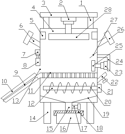
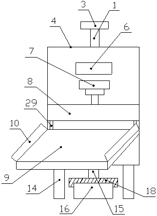
[0017] Such as Figure 1-3 As shown, a garbage compression equipment includes a compression box 4, the upper end of the compression box 4 is fixedly connected with a support column 1, the upper end of the support column 1 is fixedly connected with a support plate 3, and the lower end of the support plate 3 The middle part is fixedly connected with a hydraulic cylinder A2. The lower end of the piston rod of the hydraulic cylinder A2 penetrates the upper side wall of the compression box 4 and is fixedly connected with a pressure plate 28. The upper part of the inner wall on the left and right sides of the compression box 4 is provided with ultraviolet germicidal lamps 5 The upper part of the left and right side walls of the compression box 4 is provided with a feed port 6 symmetrically, the upper end of the feed port 6 is provided with a sealing plug 26, and the left side wall of the compression box 4 is fixedly installed with a hydraulic cylinder B7, The lower end of the piston ...

Embodiment 2

[0020] Such as Figure 1-3 As shown, a garbage compression equipment includes a compression box 4, the upper end of the compression box 4 is fixedly connected with a support column 1, the upper end of the support column 1 is fixedly connected with a support plate 3, and the lower end of the support plate 3 The middle part is fixedly connected with a hydraulic cylinder A2. The lower end of the piston rod of the hydraulic cylinder A2 penetrates the upper side wall of the compression box 4 and is fixedly connected with a pressure plate 28. The upper part of the inner wall on the left and right sides of the compression box 4 is provided with ultraviolet germicidal lamps 5 The upper part of the left and right side walls of the compression box 4 is provided with a feed port 6 symmetrically, the upper end of the feed port 6 is provided with a sealing plug 26, and the left side wall of the compression box 4 is fixedly installed with a hydraulic cylinder B7, The lower end of the piston ...


PUM


Abstract

The invention discloses a garbage compression device. The garbage compression device comprises a compression box, supporting columns are connected to the upper end of the compression box, a supportingplate is connected to the upper ends of the supporting columns, a hydraulic cylinder A is connected to the middle of the lower end of the supporting plate, a pressing plate is connected to the lowerend of a piston rod of the hydraulic cylinder A, and feeding opening are symmetrically formed in the upper parts of the left and right side walls of the compression box; a hydraulic cylinder B is installed on the left side wall of the compression box, a baffle is connected to the lower end of a piston rod of the hydraulic cylinder B, a supporting frame is connected to the right side wall of the compression box; a hydraulic cylinder C is connected to the left side of the supporting frame, a push plate is connected to the left end of a piston rod of the hydraulic cylinder C, a compression flat plate is arranged at the lower part of the compression box, and a discharge plate is connected to the left end of the compression flat plate; and a discharge opening is formed in the left side of the compression box, a deodorant injection opening is formed in the right side wall of the compression box, a drive motor is arranged on the right side wall of the compression box, a stirring shaft is connected to the output end of the drive motor, and a sewage discharge opening is formed in the middle of the lower end of the compression box. The garbage compression device has the advantages of good compression effects, high compression efficiency, long service life and high garbage recycling efficiency.

Description

Technical field [0001] The present invention relates to the technical field of garbage treatment, in particular to a garbage compression equipment. Background technique [0002] With the gradual increase in environmental protection awareness, more and more attention has been paid to the centralized treatment of garbage, and various garbage treatment equipment have also appeared. Garbage compression equipment is a relatively common type of garbage treatment equipment. The garbage compression equipment compresses the garbage. Treatment to reduce the volume, the existing garbage compression equipment has poor compression effect, short service life, can not be discharged in time, reduces compression efficiency, does not have the functions of sterilization and classification, and has low garbage recycling utilization rate. Therefore, it is urgent to design A kind of garbage with simple operation, good compression effect, long service life, can transfer the compressed block garbage out...

Claims


Application Information

Patent Timeline
Patent Type & Authority Applications(China)
IPC IPC(8): B65F1/14B65F9/00B30B9/00
CPCB30B9/00B65F1/1405B65F9/00B65F2210/162
Inventor 刘盼盼
Owner 刘盼盼
Why Eureka
Try Eureka