
Piston rod partial chrome plating device

A piston rod and partial technology, which is applied in the field of partial chrome plating of piston rod parts, can solve the problems of difficult processing, small tolerance range, and difficulty in obtaining uniform coating, and achieve the effects of improving production efficiency and easy installation and disassembly

Active Publication Date: 2019-04-16
CHINA HANGFA GUIZHOU LIYANG AVIATION POWER CO LTD
View PDF6 Cites 3 Cited by
  • Summary
  • Abstract
  • Description
  • Claims
  • Application Information

AI Technical Summary

Problems solved by technology

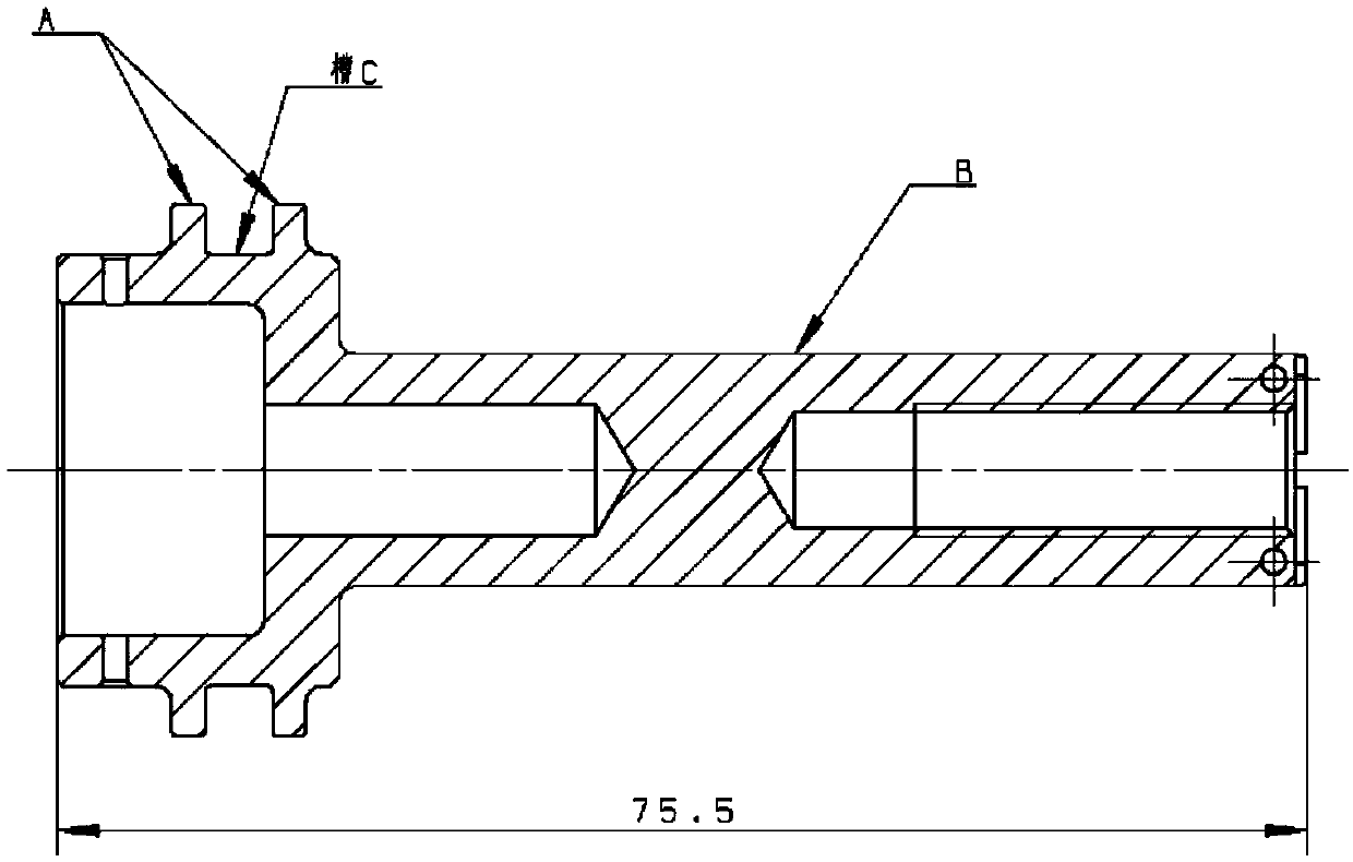
[0003] like figure 1 As shown, the piston rod requires chrome plating on the rod and the big end, and the coating thickness is required to be 4 μm to 6 μm. The tolerance range is small, the machining accuracy is high, and the processing is difficult; The location is prone to current concentration, causing the chromium layer deposition rate at the large end of the piston rod to be greater than the chromium layer deposition rate at the rod, making it difficult to obtain a uniform coating
The chrome plating of the piston rod has always had quality problems such as peeling, leakage, uneven thickness of the coating, and local chromium tumors.
[0004] In view of the above situation, it is urgent to design a piston rod chrome plating device to solve the quality problem of the piston rod chrome layer

Method used


Image

  • Piston rod partial chrome plating device
  • Piston rod partial chrome plating device
  • Piston rod partial chrome plating device

Examples


Embodiment Construction

[0030] The technical solution of the present invention will be further described below in conjunction with the accompanying drawings, but the claimed protection scope is not limited to the description.

[0031] In the present invention, if figure 1 As shown, the surface A of the large end and the surface B of the rod are required to be chrome-plated, and chrome is allowed to transition 1mm from the chrome-plated to the non-chrome-plated surface. Because the diameters of the piston rod and the big end are different, the deposition rate of the chromium layer at the big end is higher than that of the rod. In order to ensure that the uniformity of the chromium layer meets the requirements, the rod and the big end of the piston rod should be chrome-plated separately. Therefore, it is necessary to design Manufacture the chrome-plated components of the piston rod and the chrome-plated components of the large end of the piston rod.

[0032] The chrome-plated assembly of the piston ro...


PUM

PropertyMeasurementUnit
thicknessaaaaaaaaaa

Abstract

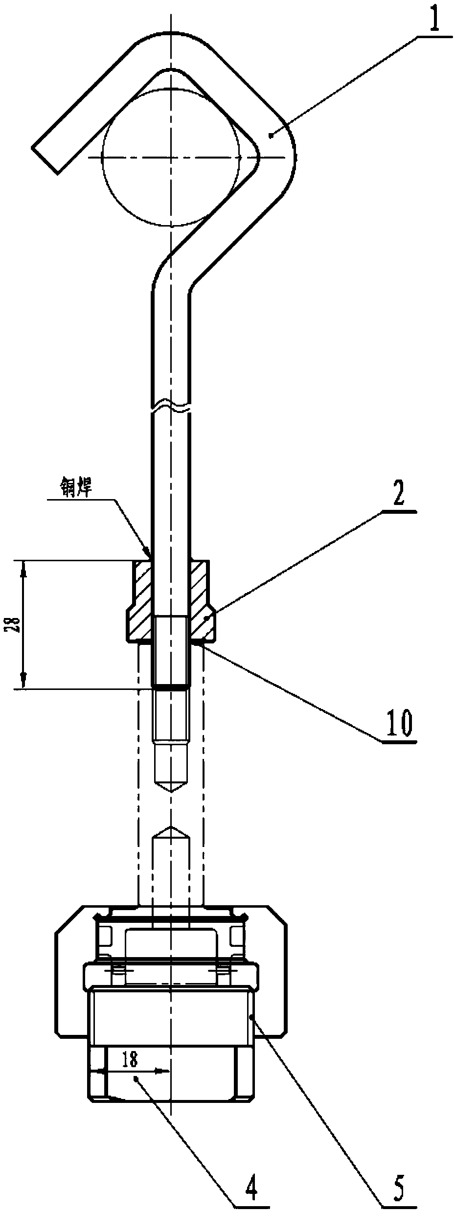
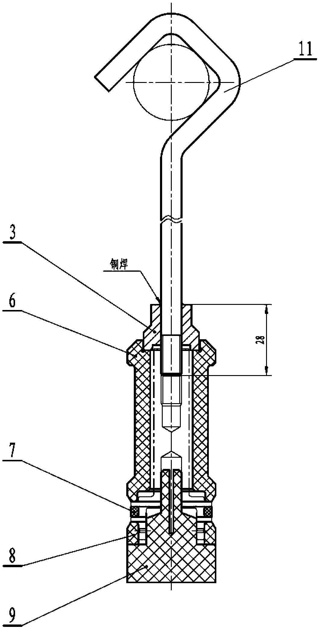
The invention discloses a piston rod partial chrome plating device. The piston rod partial chrome plating device comprises a piston rod rod-part chrome plating assembly and a big end chrome plating protection assembly, wherein the piston rod rod-part chrome plating assembly comprises a first hook (1), a first bushing (2), a gasket (10), a first plug (4) and a plug cover (5), and the big end chromeplating protection assembly comprises a second hook (11), a second bushing (3), a third bushing (6) , a rubber ring (7), a washer (8) and a second plug (9). According to the piston rod partial chromeplating device, a rod part and a big end of a piston rod are electroplated separately, the uniformity of chrome layers is easy to control, and the problems that the thickness of a chrome layer of therod part is thin and the thickness of a chrome layer of the big end is too thick are solved. When the big end is chrome plated, a groove is protected by the rubber ring, and the problem that a chromium layer remains in the groove caused by leakage of a solution is avoided. The piston rod partial chrome plating device is very easy to install and disassemble, and the production efficiency can be improved.

Description

technical field [0001] The invention relates to a device for partially chrome-plating piston rod parts, which belongs to the technical field of metal material surface treatment. Background technique [0002] The piston rod is a moving part with frequent movements, and has high technical requirements for machining accuracy, surface wear resistance, surface roughness, and high temperature resistance. The chrome-plated layer has high hardness, which can effectively improve the wear resistance and corrosion resistance of the piston rod, so as to improve the service life of the parts. [0003] Such as figure 1 As shown, the piston rod requires chrome plating on the rod and the big end, and the coating thickness is required to be 4 μm to 6 μm. The tolerance range is small, the machining accuracy is high, and the processing is difficult; The location is prone to current concentration, causing the deposition rate of the chromium layer at the large end of the piston rod to be great...

Claims


Application Information

Patent Timeline
Patent Type & Authority Applications(China)
IPC IPC(8): C25D5/02C25D3/04C25D7/00C25D17/08
CPCC25D3/04C25D5/022C25D7/00C25D17/08
Inventor 周宏标陈燕青辛丽坡刘金平
Owner CHINA HANGFA GUIZHOU LIYANG AVIATION POWER CO LTD
Learn More