Automobile waste heat recovering and reusing system

A waste heat recovery, automobile technology, applied in mechanical equipment, engine components, machines/engines, etc., can solve problems such as limited improvement space and great technical difficulty

Inactive Publication Date: 2019-04-16
JAPHL POWERTRAIN SYST
View PDF6 Cites 5 Cited by
  • Summary
  • Abstract
  • Description
  • Claims
  • Application Information

AI Technical Summary

Problems solved by technology

Improving the thermal efficiency of the engine body is a technical route, but th

Method used


Image

  • Automobile waste heat recovering and reusing system
  • Automobile waste heat recovering and reusing system
  • Automobile waste heat recovering and reusing system

Examples


Embodiment Construction

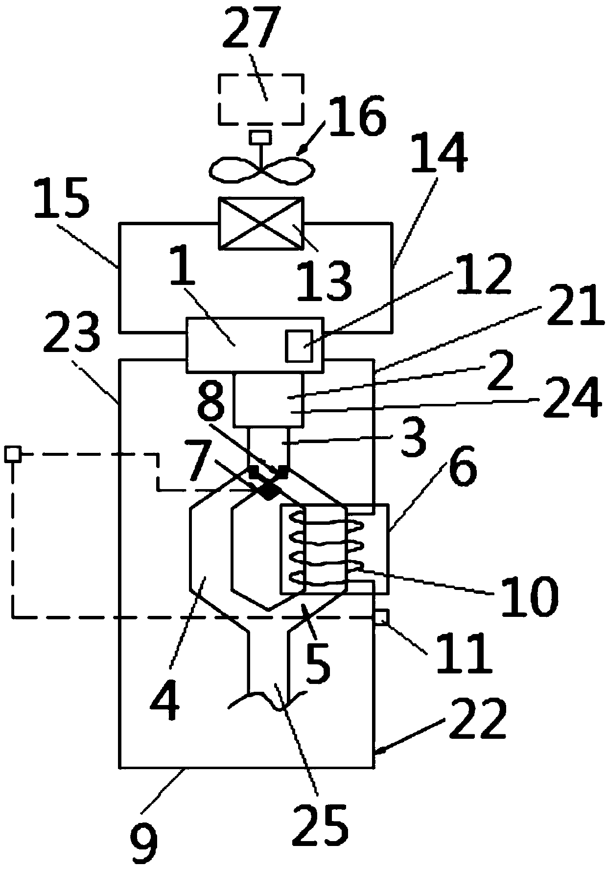
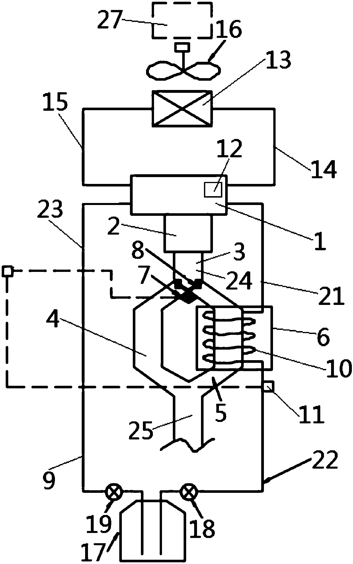
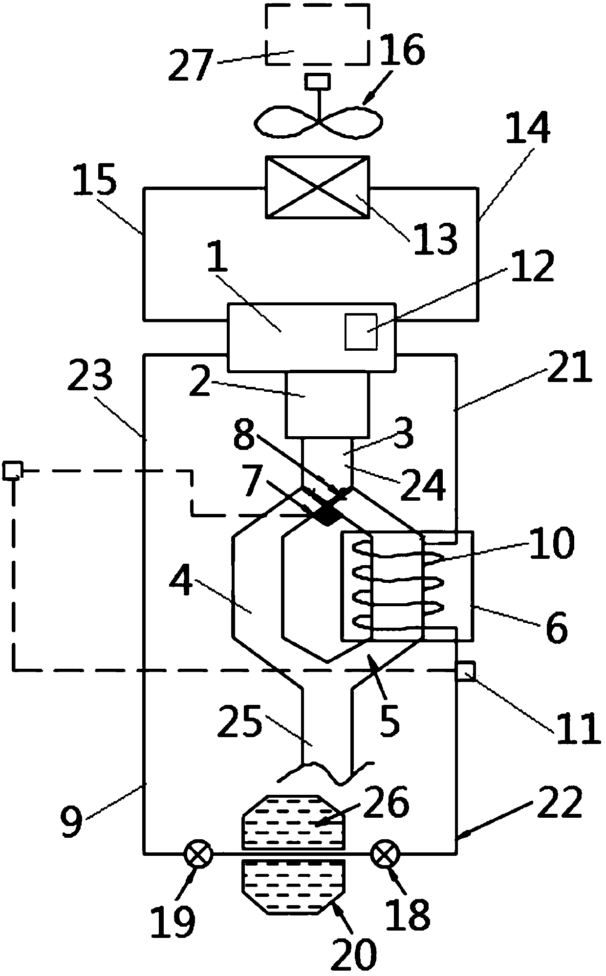
[0022] Below with reference to the accompanying drawings, through the description of the embodiments, the specific embodiments of the present invention, such as the shape, structure, mutual position and connection relationship between the various parts, the role and working principle of the various parts, etc., will be further described. Detailed instructions:

[0023] as attached figure 1As shown, the present invention is an automobile waste heat recovery and reuse system. The automobile waste heat recovery and reuse system includes an engine body 1, an exhaust manifold 2, and an exhaust pipe 3. The exhaust pipe 3 includes an exhaust Pipe branch pipeline I4 and exhaust pipe branch pipeline II5, heat exchanger 6 is arranged on exhaust pipe branch pipeline II5, bypass valve actuator 7 and bypass valve 8 are arranged on exhaust pipe 3, bypass valve The actuator 7 is arranged as a structure capable of controlling the movement of the position of the valve plate of the bypass valv...


PUM


Abstract

The invention provides an automobile waste heat recovering and reusing system applied to the technical field of automobile engines. An exhaust pipe (3) of the automobile waste heat recovering and reusing system comprises an exhaust pipe branch pipeline I (4) and an exhaust pipe branch pipeline II (5). A heat exchanger (6) is arranged on the exhaust pipe branch pipeline II (5). A bypass valve actuator (7) and a bypass valve (8) are arranged on the exhaust pipe (3). A spiral heat-exchange pipe part (10) is arranged on the portion, located in the heat exchanger (6), of a cooling liquid pipeline (9). A heat exchanger outlet cooling liquid temperature sensor (11) is arranged on the portion, stretching out of the heat exchanger (6), of the cooling liquid pipeline (9). According to the automobilewaste heat recovering and reusing system, the structure is simple; during cold starting of an automobile, part of heat in automobile exhaust can be recovered to be used for heating cooling liquid inan automobile engine cooling system, so that an engine is heated rapidly and reliably, the heat efficiency during cold starting of the engine is improved, and combustion in a cylinder is made more sufficient.

Description

technical field [0001] The invention belongs to the technical field of automobile engines, and more specifically relates to an automobile waste heat recovery and reuse system. Background technique [0002] With the global energy situation becoming more and more tense, environmental protection becoming more and more urgent, and the number of cars in various countries in the world continues to rise, traditional fuel vehicles and hybrid vehicles are facing huge pressure on energy conservation and emission reduction. For traditional automobile engines, the water temperature in the engine water jacket is low during cold start. At this time, the lubrication effect of the various parts of the engine is poor, the friction force is large, and the thermal efficiency is low. At this time, the combustion in the cylinder is relatively insufficient, so The production and emission of harmful gases are relatively high. At present, there is no good way to improve the thermal efficiency of th...

Claims


Application Information

Patent Timeline
IPC IPC(8): F01N5/02F02N19/10F01N13/08
CPCF01N5/02F01N13/08F02N19/10Y02T10/12
Inventor 杨健春严清梅范礼李后良姜倩于芳戴国民苏将兵后军亮
Owner JAPHL POWERTRAIN SYST
Why Eureka
Try Eureka