Tube-plate type heat pump system

A heat pump system, tube-sheet technology, applied in lighting and heating equipment, compressors with reversible cycle, evaporator/condenser, etc., can solve the problem of evaporator heat transfer performance attenuation, compressor damage, and difficulty in reaching critical oil Flow velocity and other issues, to prevent heat transfer performance attenuation, the effect of simple structure

Pending Publication Date: 2019-04-16
TSINGHUA UNIV
View PDF0 Cites 1 Cited by
  • Summary
  • Abstract
  • Description
  • Claims
  • Application Information

AI Technical Summary

Problems solved by technology

However, when the motor heat pump cycle is reversed, the tube-sheet heat exchanger works as a tube-sheet evaporator, and the refrigerant flows from bottom to top in the gaps inside the plates, and the flow rate is low, so it is difficult to reach the critical oil-carrying flow rate. The lubricating oil will gradually accumulate at the bottom of the evaporator, resulting in a decline in the heat transfer performance of the evaporator
At the same time, a large amount of lubricating oil cannot be returned to the compressor smoothly, making it difficult to lubricate the compressor and cause damage, and even cause damage to the compressor

Method used


Image

  • Tube-plate type heat pump system
  • Tube-plate type heat pump system
  • Tube-plate type heat pump system

Examples


Embodiment Construction

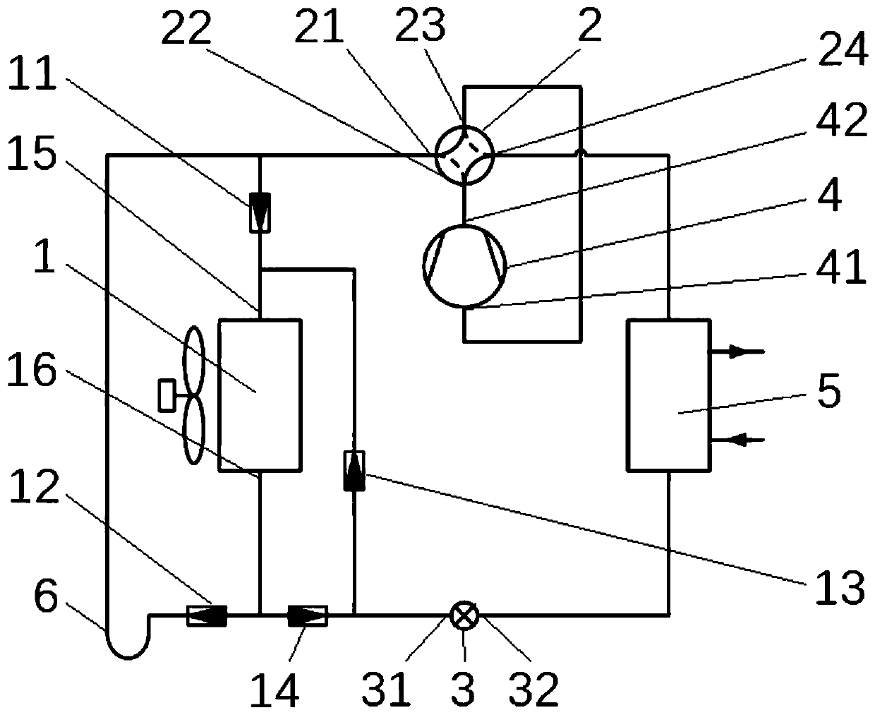
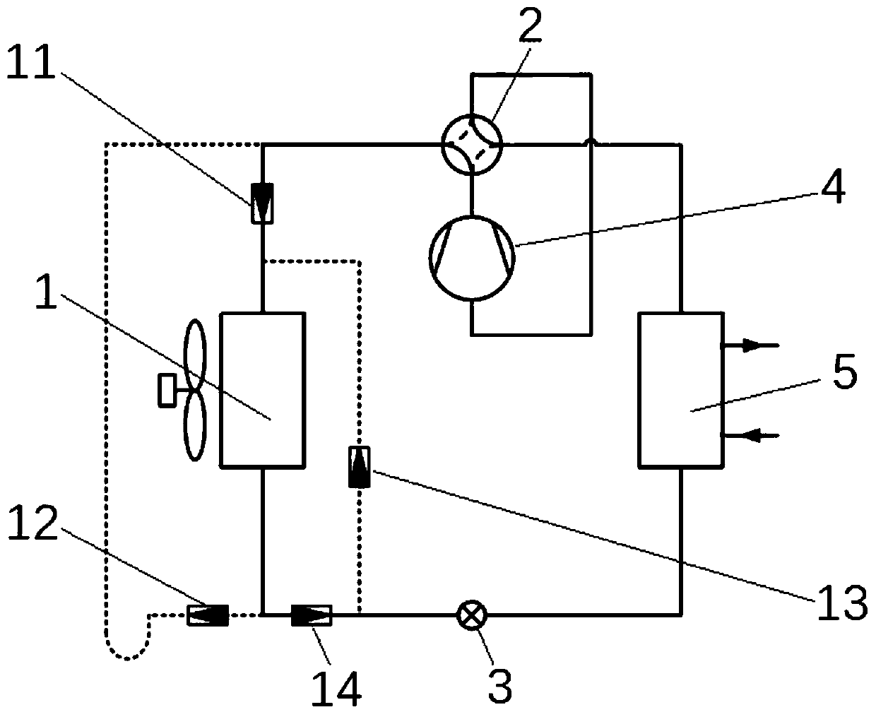
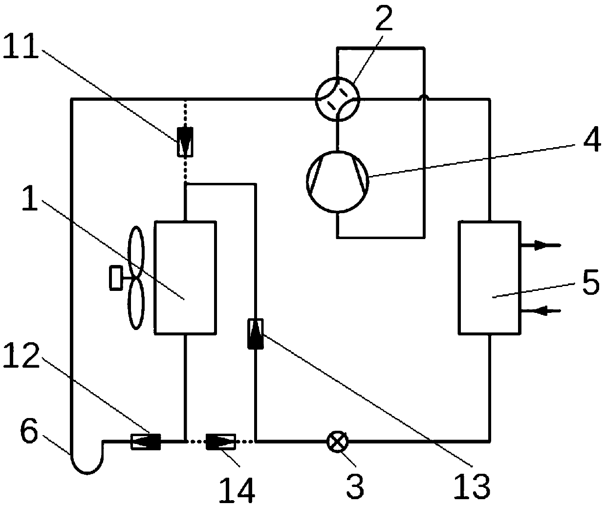
[0023] The specific implementation manners of the present invention will be further described in detail below in conjunction with the accompanying drawings and embodiments. The following examples are used to illustrate the present invention, but are not intended to limit the scope of the present invention.

[0024] In the description of the present invention, it should be noted that the terms "center", "longitudinal", "transverse", "upper", "lower", "front", "rear", "left", "right", " The orientations or positional relationships indicated by "vertical", "horizontal", "top", "bottom", "inner", "outer", etc. are based on the orientation or positional relationships shown in the drawings, and are only for the convenience of describing the present invention and simplifying Describes, but does not indicate or imply that the device or element referred to must have a specific orientation, be constructed in a specific orientation, and operate in a specific orientation, and therefore sh...


PUM


Abstract

The invention relates to the technical field of heat pump air conditioning, and discloses a tube-plate type heat pump system comprising a four-way valve, a throttling valve and a tube-plate type heatexchanger. The tube-plate type heat exchanger comprises an inlet end arranged on the top and an outlet end arranged at the bottom. The tube-plate type heat pump system further comprises a first three-way piece. Three ports of the first three-way piece are connected with a first port, an inlet end and an outlet end of the four-way valve correspondingly. The tube-plate type heat pump system furthercomprises a second three-way piece. Three ports of the second three-way piece are connected with a first port, an inlet end and an outlet end of the throttling valve correspondingly. According to thetube-plate type heat pump system, by arranging the first three-way piece and the second three-way piece, a circulation refrigerant mixed with lubricating oil flows from top to bottom in the tube-platetype heat exchanger both in the refrigerating circulation working condition mode and the heating circulation working condition mode; the problem that the refrigerant accumulates at the tube bottom when flowing in gaps in sheets from bottom to top is solved; the tube-plate type heat pump system is simple in structure, convenient to use and practical; and by means of the tube-plate type heat exchanger, the aim of achieving two purposes through one machine can be better achieved.

Description

technical field [0001] The invention relates to the technical field of heat pump air conditioners, in particular to a tube-sheet heat pump system. Background technique [0002] When the heat pump system is working, a small amount of lubricating oil will be carried by the refrigerant out of the compressor, and part of it will be separated by the oil separator on the exhaust pipe and returned to the compressor, but the other part will still enter the heat pump cycle with the refrigerant, that is, enter evaporation condenser and condenser. For the traditional tube heat exchanger, since the refrigerant flows at high speed in the circular tube, it can bring the lubricating oil back to the compressor. For the tube-sheet heat exchanger, the entire heat exchanger is composed of plates, and the refrigerant flows between the narrow gaps in the plates. When the existing tube-sheet heat exchanger works as a tube-sheet condenser in summer, the refrigerant flows from top to bottom in th...

Claims


Application Information

Patent Timeline
Patent Type & Authority Applications(China)
IPC IPC(8): F25B13/00F25B41/04F25B39/00F25B41/20
CPCF25B13/00F25B39/00F25B2313/027F25B41/20
Inventor 石文星宋鹏远王宝龙李先庭
Owner TSINGHUA UNIV
Why Eureka
Try Eureka