Novel phase change heat storage heat exchanger and working method

A heat storage heat exchanger and phase change heat storage technology, which is applied in the direction of indirect heat exchangers, heat exchanger types, heat storage equipment, etc., can solve the problem that heat storage bodies cannot transfer heat to each other, heat storage time prolongs, and effect time Long and other problems, to achieve good heat storage effect, improve stability, and large contact area

Inactive Publication Date: 2019-04-16
SHANDONG UNIV
View PDF7 Cites 5 Cited by
  • Summary
  • Abstract
  • Description
  • Claims
  • Application Information

AI Technical Summary

Problems solved by technology

However, this kind of heat storage technology has certain shortcomings. Due to the non-direct contact heat exchange form, the effect time i

Method used


Image

  • Novel phase change heat storage heat exchanger and working method
  • Novel phase change heat storage heat exchanger and working method

Examples


Embodiment 1

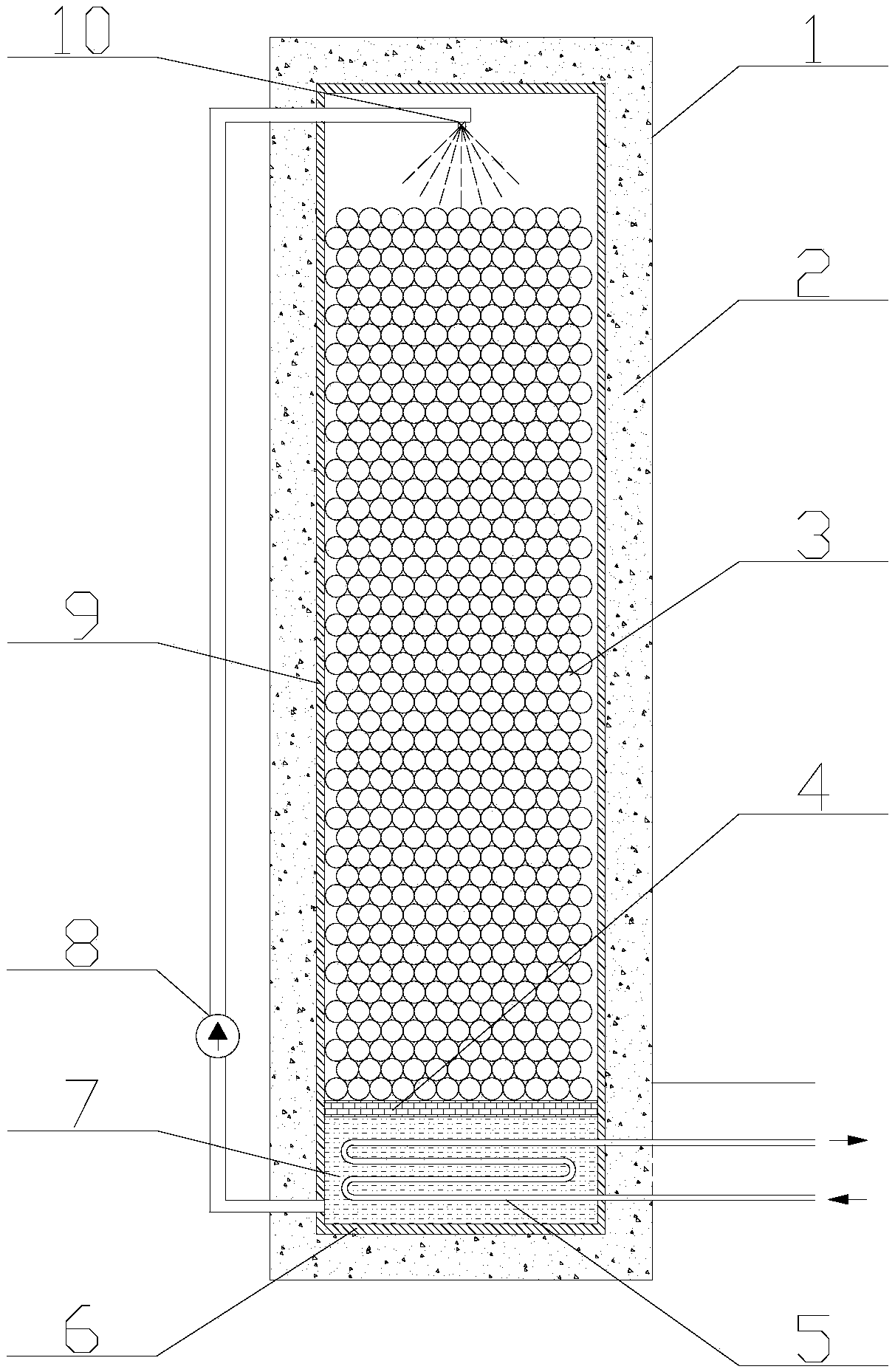
[0032] In some embodiments, a novel heat exchange tube type phase change heat storage heat exchange device is disclosed, such as figure 1 As shown, it includes a heat storage heat exchanger shell 1 , an insulation layer 2 , an adsorption heat storage material 3 , an orifice plate 4 , a heat exchange tube 5 , a heat exchange medium 7 , a heat exchange medium circulation pump 8 and an atomizing nozzle 10 .

[0033] The heat storage heat exchanger housing 1 is a cuboid or cylinder, made of pressure-resistant materials, such as cast iron or stainless steel, and an insulating layer 2 is arranged inside. The thermal insulation layer 2 is made of materials with thermal insulation and waterproof functions, and foam materials, such as polyurethane foam materials, can be used.

[0034] The inside of the heat storage heat exchanger casing 1 is in a vacuum state.

[0035] The heat storage heat exchanger housing 1 is divided into upper and lower parts. The heat storage medium box 9 is arr...

Embodiment 2

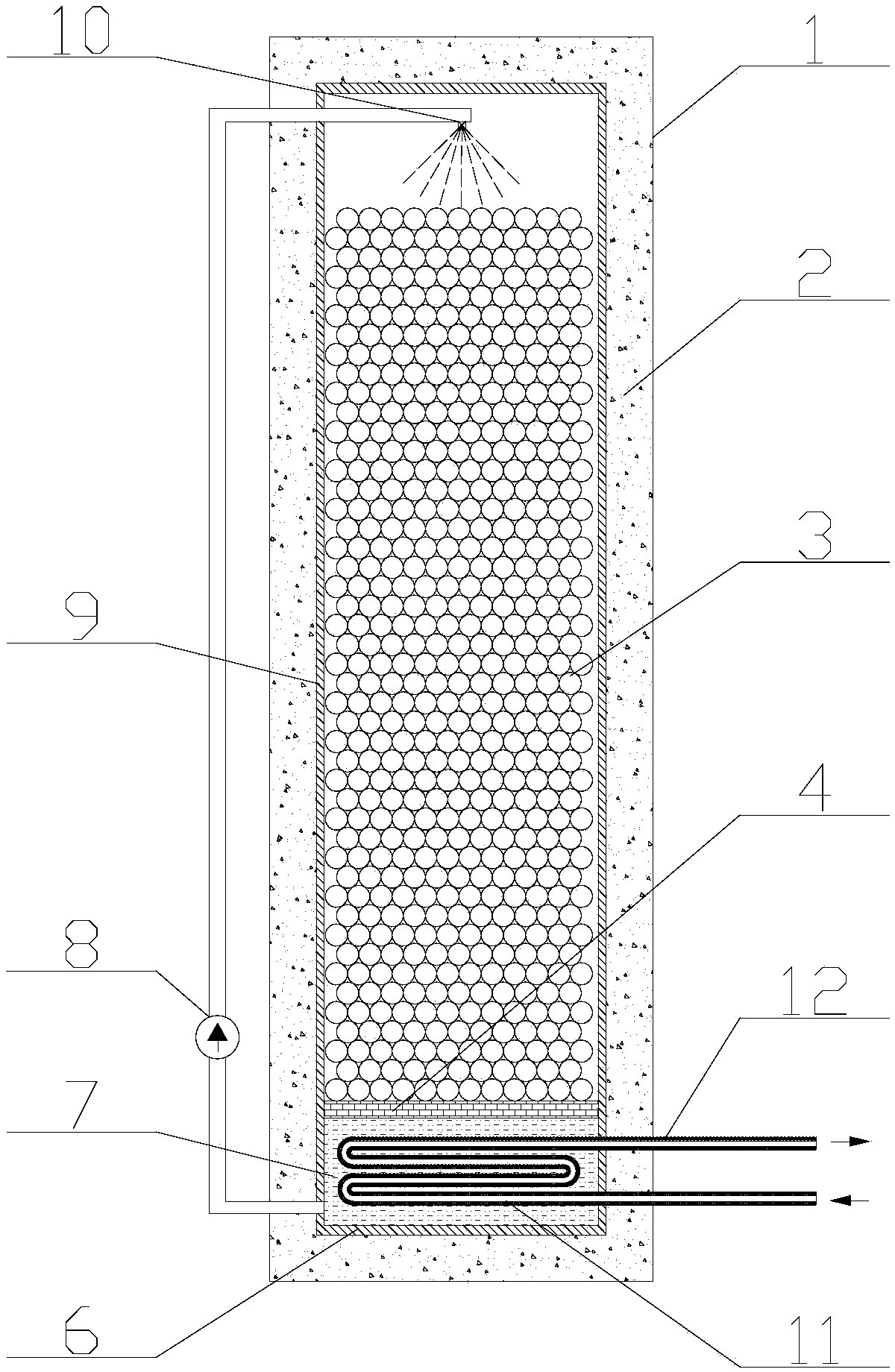
[0047] In some embodiments, a novel heat exchange tube type phase change heat storage heat exchange device is disclosed, such as figure 2 As shown, it includes: heat storage heat exchanger shell 1, insulation layer 2, adsorption heat storage material 3, orifice plate 4, heat exchange medium 7, heat exchange medium circulation pump 8, atomizing nozzle 10 and heat pipe 11.

[0048] The heat storage heat exchanger housing 1 is a cuboid or cylinder, made of pressure-resistant materials, such as cast iron or stainless steel, and an insulating layer 2 is arranged inside. The thermal insulation layer 2 is made of materials with thermal insulation and waterproof functions, and foam materials, such as polyurethane foam materials, can be used.

[0049] The inside of the heat storage heat exchanger housing 1 is in a certain negative pressure state.

[0050] The heat storage heat exchanger shell 1 is divided into upper and lower parts, with a heat storage medium box 9 on the upper side ...


PUM


Abstract

The invention discloses a novel phase change heat storage heat exchanger and a working method of the novel phase change heat storage heat exchanger. The novel phase change heat storage heat exchangercomprises a heat storage heat exchanger shell, the heat storage heat exchanger shell is internally provided with a heat insulation layer, a cavity inside the heat insulation layer is divided into an upper part and a lower part by an orifice plate, the upper part of the cavity is provided with a heat storage medium, the lower part of the cavity is provided with a heat exchange medium, the lower part of the cavity communicates with the top of the upper part of the cavity through a pipe, the pipe is provided with a circulation pump, and the cavity inside the heat insulation layer is in a vacuum state or a negative pressure state. The novel phase change heat storage heat exchanger has the beneficial effects that heat is transferred to the heat exchange medium through a heat exchange pipe or aheat pipe, the heat exchange medium is transported to the upper part of a tank through the circulation pump for atomization spraying, the medium and the heat storage medium in the tank are subjected to heat exchange, and therefore a good heat storage effect is obtained.

Description

technical field [0001] The invention relates to a novel phase-change heat storage and heat exchange technology, which is mainly used in the fields of energy and chemical industry, aerospace, military industry, air conditioning and refrigeration, and is especially suitable for occasions requiring heat storage. Background technique [0002] Heat storage technology is a technology that uses heat storage energy storage materials for energy storage. According to the heat storage method, it can be divided into sensible heat storage, phase change heat storage, thermochemical heat storage and adsorption heat storage. Compared with several other forms of heat storage, phase change heat storage refers to the storage and release of energy by utilizing the material characteristics of the heat storage medium to absorb or release a large amount of latent heat of phase change during the phase change process. In the cycle process of heat storage and energy release, the grade and use time of...

Claims


Application Information

Patent Timeline
IPC IPC(8): F28D20/02F28D20/00F28D15/02F28F1/00
CPCF28D15/02F28D20/00F28D20/003F28D20/023F28D2020/0065F28D2020/0078F28F1/00Y02E60/14
Inventor 徐夕仁周淼王晓哲崔琳
Owner SHANDONG UNIV
Why Eureka
Try Eureka