Photon radiation microscope sample holder, testing method and microscope device
A technology of photon radiation and microscopy, applied in microscopes, measuring devices, electronic circuit testing, etc., can solve the problems of inability to accurately locate the Hotspot position, 100X probes cannot be focused, and easily damage samples and probes, etc., so as to broaden the scope of use and improve The efficiency of failure analysis and the effect of saving testing costs
- Summary
- Abstract
- Description
- Claims
- Application Information
AI Technical Summary
Problems solved by technology
Method used
Image
Examples
Embodiment 1
[0042] Embodiment 1 sample holder
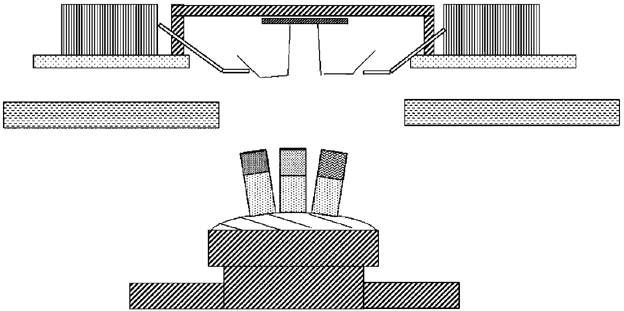
[0043] Such as Figure 4-8 As shown, the photon radiation microscope sample holder 10 of the present invention includes: a substrate 11 , a metal electrode 13 , a support 15 , a base 16 , and a bonding wire 14 .
[0044]The substrate 11 is preferably a square PCB board. Preferably, the substrate 11 has a side length of 50-80 mm and a height of 5 mm. The substrate is provided with a sample carrying area for carrying samples; the sample carrying area runs through the substrate along the vertical direction; the sample carrying area is provided with a carrying plate 12 of light-transmitting material; preferably, the carrying Plate 12 is a quartz glass plate. In this embodiment, the quartz glass plate is arranged in the central area of the substrate, the side length of the quartz glass plate is 25-50 mm, and the height is 3 mm.
[0045] The metal electrode 13 is arranged in the substrate and penetrates the substrate along the vertical direct...
Embodiment 2
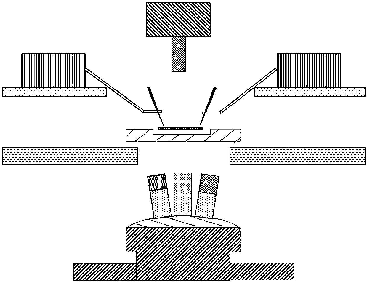
[0049] Embodiment 2 Backside Detection Photon Radiation Microscope Equipment and Detection Method
[0050] Such as Figure 9 Shown, the photon radiation microscope equipment of a preferred embodiment of the present invention, it is the photon radiation microscope equipment of back detection type, and it comprises: Probe seat 20, equipment carrying platform 30, optical lens 40, detector 50, observation microscope 60.
[0051] The probe base 20 has an upper surface for supporting the probe base 20 , a probe arm 21 is disposed on the probe base 20 , and a probe 22 is disposed on the probe arm 21 .
[0052] The equipment carrying platform 30 is used for carrying the sample holder of the photon radiation microscope.
[0053] The optical lens 40 is arranged below the sample stage and the probe stage for optical focusing, and there is a gap between the optical lens 40 and the equipment carrying table 30, the probe holder 20, the probe arm 21 and the probe 22. The safe working dist...
Embodiment 3
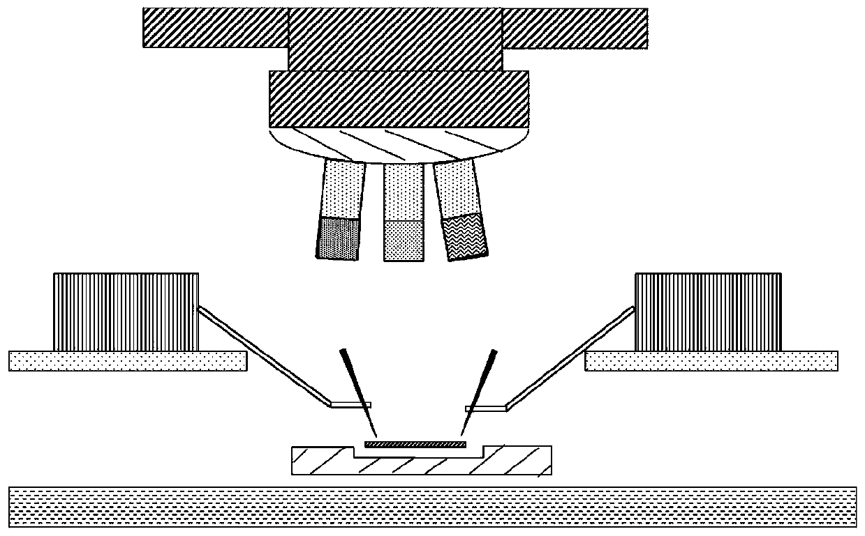
[0061] Embodiment 3 Front-side detection photon radiation microscope equipment and detection method
[0062] Such as Figure 10 As shown, the photon radiation microscope device of a preferred embodiment of the present invention is a front-side detection photon radiation microscope device, which includes: a probe base 20 , a device carrier 30 , an optical lens 40 , and a detector 50 .
[0063] The probe base 20 has an upper surface for supporting the probe base 20 , a probe arm 21 is disposed on the probe base 20 , and a probe 22 is disposed on the probe arm 21 .
[0064] The equipment carrying platform 30 is used for carrying the sample holder of the photon radiation microscope.
[0065] The optical lens 40 is arranged above the sample stage and the probe stage for optical focusing, and there is a gap between the optical lens 40 and the equipment carrying table 30, the probe holder 20, the probe arm 21 and the probe 22. The safe working distance, the optical lens described i...
PUM
 Abstract
Description
Claims
Application Information
 - R&D
- Intellectual Property
- Life Sciences
- Materials
- Tech Scout
- Unparalleled Data Quality
- Higher Quality Content
- 60% Fewer Hallucinations
Browse by: Latest US Patents, China's latest patents, Technical Efficacy Thesaurus, Application Domain, Technology Topic, Popular Technical Reports.
© 2025 PatSnap. All rights reserved.Legal|Privacy policy|Modern Slavery Act Transparency Statement|Sitemap|About US| Contact US: help@patsnap.com


