Method for carrying out plate-shaped closed-loop control by adopting plate-shaped simulation system by continuous annealing unit

A technology of simulation system and continuous annealing unit, which is applied in the field of metallurgy, can solve the problems that the shape change cannot be improved through the corresponding control system, and the continuous annealing unit cannot be equipped with flatness measuring rollers and corresponding control systems, etc.

Inactive Publication Date: 2019-04-16
SHANDONG UNIV OF SCI & TECH
View PDF6 Cites 0 Cited by
  • Summary
  • Abstract
  • Description
  • Claims
  • Application Information

AI Technical Summary

Problems solved by technology

[0003] The purpose of the present invention is to provide a continuous annealing unit for the problem that the continuous annealing unit (especially the furnace section) cannot be equipped with a flatness measuring roll

Method used


Image

  • Method for carrying out plate-shaped closed-loop control by adopting plate-shaped simulation system by continuous annealing unit
  • Method for carrying out plate-shaped closed-loop control by adopting plate-shaped simulation system by continuous annealing unit
  • Method for carrying out plate-shaped closed-loop control by adopting plate-shaped simulation system by continuous annealing unit

Examples


Embodiment 1

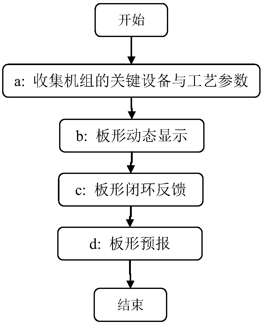
[0083] Taking the use of the plate shape simulation system by a continuous annealing unit in a domestic steel mill as an example, combined with figure 1 , the method of using the flatness simulation system to carry out flatness closed-loop control in the continuous annealing unit is described in detail, and the specific steps are as follows:

[0084] (a) Collect the key equipment and process parameters of the unit, mainly including: the total number of process sections in the furnace of the continuous annealing unit is 7, and they are numbered 1···7 in sequence, and the maximum value of tension σ set in each process section is collected j,max ={8.3,6.9,7.3,7.1,10.3,10.5,12.3}(MPa) and minimum value σ j,min ={7.7,6.2,6.4,6.3,9.5,9.7,11.5} (MPa), furnace roll body curve D(x) 1 ={448.71,448.85,449,449.14,449.28, 449.43,449.57,449.72,449.86,450,450,450,450,450,450,450 449.86,449.72,449.57,449.43,449.28,449.14,449,448.85,448.71 }, D(x) 2 ={449.29, 449.40, 449.51, 449.62, 449.72, ...

Embodiment 2

[0128] Taking the use of the flatness simulation system by a continuous annealing unit in a domestic steel mill as an example, the flatness simulation system is used for the continuous annealing unit to perform flatness closed-loop control. The specific steps are as follows:

[0129] (a) Collect the key equipment and process parameters of the unit, mainly including: the total number of process sections in the furnace of the continuous annealing unit is 7, and they are numbered 1···7 in sequence, and the maximum value of tension σ set in each process section is collected j,max ={8.3,6.9,7.3,7.1,10.3,10.5,12.3}(MPa) and minimum value σ j,min ={7.7,6.2,6.4,6.3,9.5,9.7,11.5} (MPa), furnace roll body curve D(x) 1 ={448.71,448.85,449,449.14,449.28, 449.43,449.57,449.72,449.86,450,450,450,450,450,450,450 449.86,449.72,449.57,449.43,449.28,449.14,449,448.85,448.71 }, D(x) 2 ={449.29, 449.40, 449.51, 449.62, 449.72, 449.83, 449.94, 450, 450, 450, 450, 450, 450, 450, 450, 450, 450, 450...


PUM


Abstract

The invention discloses a method for carrying out plate-shaped closed-loop control by adopting a plate-shaped simulation system by a continuous annealing unit. The method comprises the following stepsexecuted by a computer that (a) key equipment and process parameters of the unit are collected, wherein the parameters comprise total process section number in the continuous annealing unit, the maximum values and the minimum values of tension in the process sections, furnace roller body curves, distance between every two adjacent furnace roller center lines and strip steel temperature differencepolynomial coefficients of the process sections; (b) plate-shaped is dynamically displayed; (c) plate-shaped closed-loop feedback is conducted; and (d) plate-shaped forecast is conducted. According to the method, on the premise that a solid plate-shaped measuring roller and the corresponding control system are not configured, the dynamic visual display and closed-loop control of the plate shape are realized, the additional functions of plate shape forecast and the like are further achieved, and the stable plate passing through in continuous annealing projects can be effectively ensured, and the plate-shaped quality of finished strip steel is improved.

Description

technical field [0001] The invention belongs to the technical field of metallurgy, and in particular relates to a method for closed-loop control of plate shape of a continuous annealing unit. Background technique [0002] In recent years, with the increasingly fierce competition in the steel market, most strip users have shifted from low-end to high-end, and the requirements for the shape quality of products are getting higher and higher. The whole-process shape control idea has been gradually adopted by steel companies. As an important process in the production process of high-grade cold-rolled strip products, continuous annealing provides raw materials for the subsequent smoothing process, and its shape accuracy plays a decisive role in the shape of the finished product. The change of strip steel shape in the process of continuous stripping exists objectively, and the on-site technicians have long recognized this, but the available adjustment methods are limited, and they ...

Claims


Application Information

Patent Timeline
IPC IPC(8): G05B17/02C21D11/00C21D1/26C21D9/52
CPCC21D1/26C21D9/52C21D11/00G05B17/02
Inventor 王瑞李勇杨德星苏春建吕玉廷
Owner SHANDONG UNIV OF SCI & TECH
Why Eureka
Try Eureka