
Lead-acid storage battery positive electrode plate processing method and application of lead-acid storage battery

A technology of lead-acid battery and processing method, which is applied in the direction of lead-acid battery electrode, lead-acid battery, lead-acid battery construction, etc., which can solve the problems of increased electrode plate spacing, slow charging and discharging, and poor activity of coating materials for the two electrodes. To achieve the effect of improving the workshop environment, increasing production efficiency and improving efficiency

Inactive Publication Date: 2019-04-16
孟婷婷
View PDF7 Cites 2 Cited by
  • Summary
  • Abstract
  • Description
  • Claims
  • Application Information

AI Technical Summary

Problems solved by technology

[0004] Since the current lead-acid battery is forced to thicken the positive and negative plates and solidify the active material in order to ensure the strength of the plates to avoid breakage and the attached lead paste to fall off, and the thickening of the plates will also increase the amount of sulfuric acid injected into the medium. This in turn leads to the thickening of the glass fiber separator and the separator. The thickening of the separator will lead to an increase in the distance between the opposite plates, and the poor activity of the two-pole coating material will cause the conductivity of the plate material to be insufficient.
These are the reasons for the low energy density and slow charging and discharging of lead-acid batteries.
[0005] In short, the lead-acid batteries in the prior art have certain defects in terms of volume, storage capacity and charging time, etc., which limit the application range of lead-acid batteries

Method used

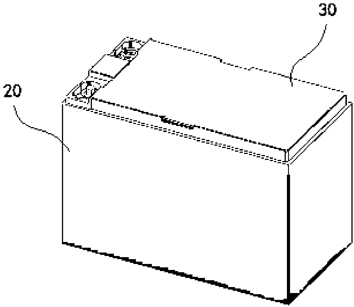
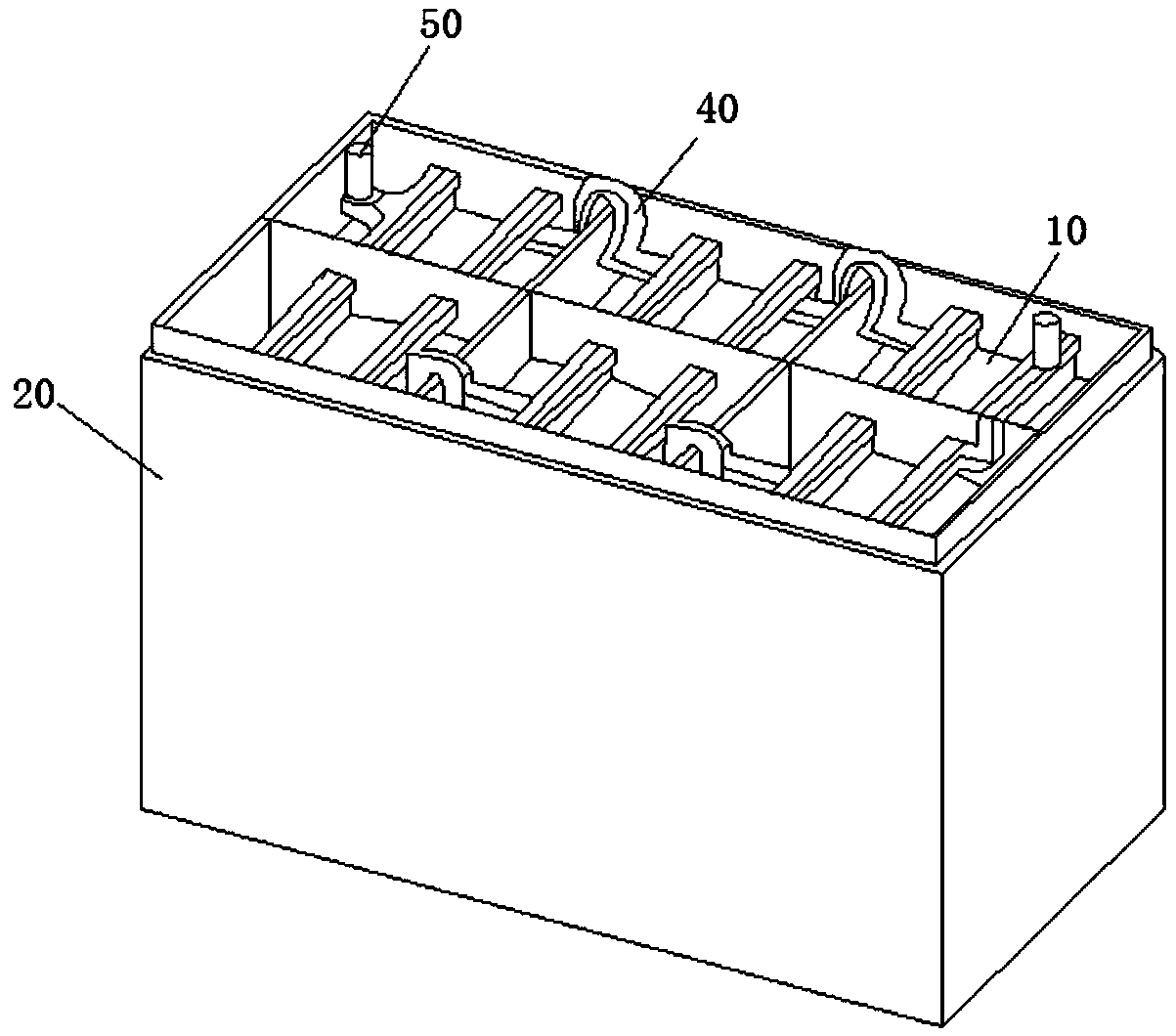
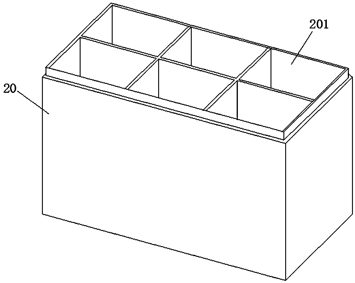

Image

  • Lead-acid storage battery positive electrode plate processing method and application of lead-acid storage battery
  • Lead-acid storage battery positive electrode plate processing method and application of lead-acid storage battery
  • Lead-acid storage battery positive electrode plate processing method and application of lead-acid storage battery

Examples


Embodiment Construction

[0030] The technical solutions in the embodiments of the present invention will be clearly and completely described below in conjunction with the embodiments of the present invention. Apparently, the described embodiments are only some of the embodiments of the present invention, not all of them. Based on the embodiments of the present invention, all other embodiments obtained by persons of ordinary skill in the art without making creative efforts belong to the protection scope of the present invention.

[0031] In the description of the present invention, it should be noted that the orientation or positional relationship indicated by the terms "vertical", "upper", "lower" and "horizontal" are based on the orientation or positional relationship shown in the drawings, and are only for It is convenient to describe the utility and simplify the description, but does not indicate or imply that the device or element referred to must have a specific orientation, be constructed and ope...


PUM

PropertyMeasurementUnit
thicknessaaaaaaaaaa
thicknessaaaaaaaaaa
pore sizeaaaaaaaaaa

Abstract

A lead-acid storage battery positive electrode plate processing method is characterized in that a first AGM separator, a second AGM separator, a positive electrode plate grid and positive electrode fluid lead paste are included; wherein the positive electrode fluid lead paste is attached to the upper surface of the first AGM separator, the positive electrode plate grid is laid on the positive electrode fluid lead paste, a layer of positive electrode fluid lead paste is attached to the upper surface of the positive electrode plate grid, and the second AGM separator is laid on the positive electrode fluid lead paste. The storage battery electrode plate is made into a module structure and then assembled, so that the production efficiency is greatly improved, the limitation that the electrodeplate needs to be independently prepared and then assembled in the traditional changelesslead-acid storage battery machining process is broken through, the electrode plate group is prepared by adopting a 3D printing method, various mechanical equipment is omitted, and the efficiency is obviously improved.

Description

technical field [0001] The invention relates to the technical field of lead-acid batteries, in particular to a method for processing positive plates of lead-acid batteries and applications thereof. Background technique [0002] Lead storage battery is a battery system invented by Plant in 1859. It has a history of more than 100 years and is the most widely used chemical power source in the world. Although new batteries such as nickel-cadmium batteries, nickel-metal hydride batteries, and lithium-ion batteries have been introduced and applied in recent years, lead-acid batteries still rely on high-current discharge performance, stable voltage characteristics, wide temperature range, and large single-cell capacity. A series of advantages such as high safety, abundant and renewable raw materials, and low price occupy a firm position in most traditional fields and some emerging application fields. However, lead-acid batteries have the disadvantages of low energy density and slo...

Claims


Application Information

Patent Timeline
Patent Type & Authority Applications(China)
IPC IPC(8): H01M4/16H01M4/20H01M4/21H01M10/12
CPCH01M4/16H01M4/20H01M4/21H01M10/12Y02E60/10Y02P70/50
Inventor 孟婷婷尚圣杰
Owner 孟婷婷
Learn More