Battery heat exchange device, power battery assembly and power automobile

A technology for heat exchange devices and power batteries, applied in electrical components, secondary batteries, circuits, etc., can solve problems such as inconsistent temperature distribution of battery modules, improve temperature consistency, increase heat exchange efficiency, and prolong service life Effect

Inactive Publication Date: 2019-04-16
FARASIS TECH (GANZHOU) CO LTD
View PDF4 Cites 3 Cited by
  • Summary
  • Abstract
  • Description
  • Claims
  • Application Information

AI Technical Summary

Problems solved by technology

[0005] The purpose of the present invention is to overcome the defect of inconsistent temperature distribution of the battery module caused by the uneven temperature distribution of the heat conduction plate used for battery heat exchange in the prior art, and to provide a battery heat exchange device, For power battery components and power vehicles, the battery heat exchange device arranges a layer of heat-conducting coating on the surface of the heat-conducting plate, so that the heat of the heat-conducting plate can be quickly and uniformly transferred to the surface of the heat-conducting coating during the heating and cooling process, thereby improving the The heat exchange efficiency of the battery also greatly improves the temperature consistency of the battery cells in the battery system, thereby prolonging the service life of the battery

Method used


Image

  • Battery heat exchange device, power battery assembly and power automobile
  • Battery heat exchange device, power battery assembly and power automobile
  • Battery heat exchange device, power battery assembly and power automobile

Examples


Embodiment 1

[0041] This embodiment is used to illustrate the structural composition and working principle of the battery heat exchange device and the power battery assembly.

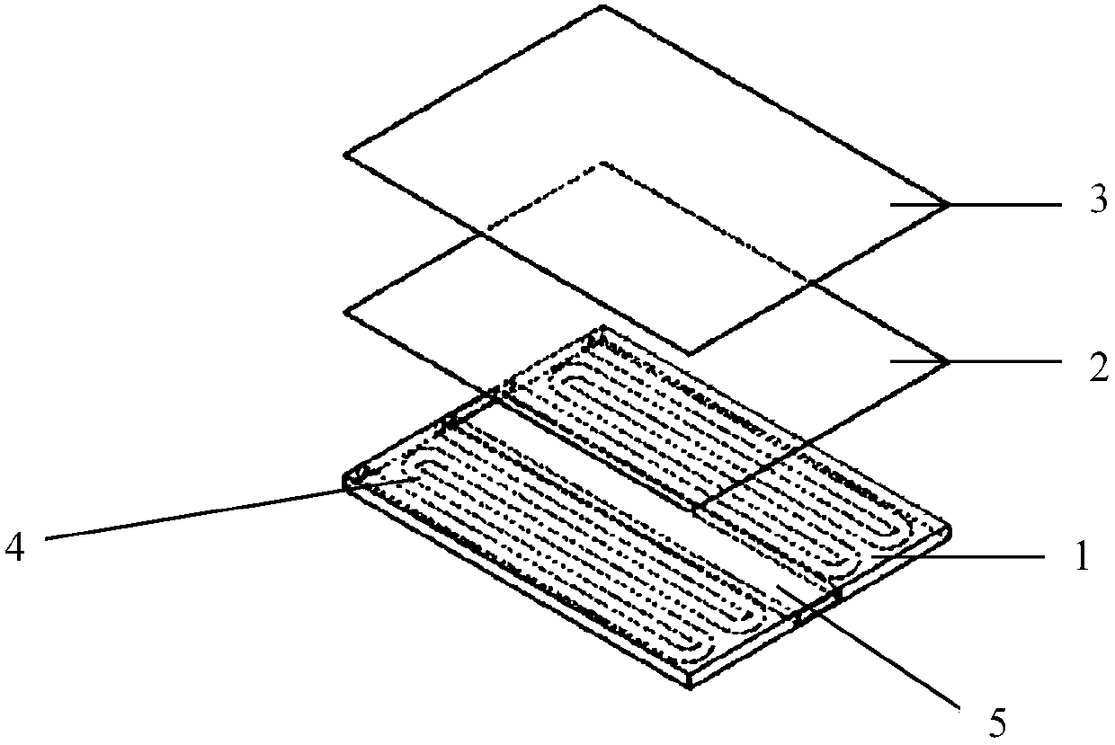
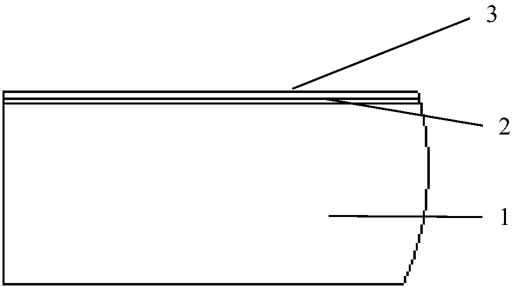
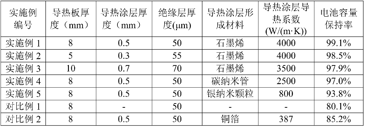
[0042] The schematic diagram of the structure of the battery heat exchange device provided by the present invention is as follows: figure 1 with figure 2 As shown, the battery heat exchange device includes a heat conduction plate 1, a heat conduction coating 2 and an insulating layer 3 arranged in sequence from bottom to top, wherein the thickness of the heat conduction plate 1 is 8mm, and the thickness of the heat conduction coating 2 is The thickness is 0.5 mm, and the thickness of the insulating layer 3 is 50 μm. In the battery heat exchange device, the material of the heat conducting plate 1 is 6063 aluminum alloy, and its thermal conductivity is 202.4W / (m·K); the forming material of the heat conducting coating 2 is graphene, and its thermal conductivity is is 4000W / (m·K); the insulating layer 3 is made of PE...

Embodiment 2

[0046] This embodiment is used to illustrate the structural composition and working principle of the battery heat exchange device and the power battery assembly.

[0047] The schematic diagram of the structure of the battery heat exchange device provided by the present invention is as follows: figure 1 with figure 2 As shown, the battery heat exchange device includes a heat conduction plate 1, a heat conduction coating 2 and an insulating layer 3 arranged in sequence from bottom to top, wherein the thickness of the heat conduction plate 1 is 5 mm, and the thickness of the heat conduction coating 2 is The thickness is 0.3 mm, and the thickness of the insulating layer 3 is 55 μm. In the battery heat exchange device, the material of the heat conducting plate 1 is 6063 aluminum alloy, and its thermal conductivity is 202.2W / (m·K); the forming material of the heat conducting coating 2 is graphene, and its thermal conductivity is is 4000W / (m·K); the insulating layer 3 is made of P...

Embodiment 3

[0051] This embodiment is used to illustrate the structural composition and working principle of the battery heat exchange device and the power battery assembly.

[0052] The schematic diagram of the structure of the battery heat exchange device provided by the present invention is as follows: figure 1 with figure 2 As shown, the battery heat exchange device includes a heat conducting plate 1, a heat conducting coating 2 and an insulating layer 3 arranged in sequence from bottom to top, wherein the thickness of the heat conducting plate 1 is 10mm, and the thickness of the heat conducting coating 2 is The thickness is 0.7 mm, and the thickness of the insulating layer 3 is 70 μm. In the battery heat exchange device, the material of the heat conducting plate 1 is 6063 aluminum alloy, and its thermal conductivity is 202.2W / (m·K); the forming material of the heat conducting coating 2 is graphene, and its thermal conductivity is is 3500W / (m·K); the insulating layer 3 is made of P...


PUM

PropertyMeasurementUnit
Thicknessaaaaaaaaaa
Thicknessaaaaaaaaaa
Thicknessaaaaaaaaaa

Abstract

The invention relates to the field of battery heat exchange, and discloses a battery heat exchange device, a power battery assembly and a power automobile. The battery heat exchange device comprises aheat conducting plate, a heat conducting coating and an insulating layer which are sequentially arranged from bottom to top, and the heat conductivity coefficient of a material forming the heat conducting coating is 800 W / (m.K) or above, preferably 3000-5780W / (m.K). According to the battery heat exchange device, the heat conducting coating is arranged on the surface of the heat conducting plate,so that heat can be quickly and uniformly conducted to the surface of the heat conducting coating in the heating and cooling processes of the heat conducting plate, the heat exchange efficiency of thebattery is improved, the temperature consistency of battery cells in the battery at different positions in the same horizontal section is greatly improved, and the service life of the battery is prolonged. The power battery assembly formed by assembling the battery heat exchange device and the battery is particularly suitable for being used as a power battery assembly on a pure electric vehicle or a hybrid electric vehicle so as to meet different heat exchange conditions required by the battery under different running working conditions and environments of the power vehicle.

Description

technical field [0001] The invention relates to the field of battery heat exchange, in particular to a battery heat exchange device, a power battery assembly and a power vehicle. Background technique [0002] At present, with the rapid development of the new energy industry, batteries are more widely used, such as in automobiles. By using power battery systems to provide electric energy for electric vehicles, electric energy can become the power source of electric vehicles and reduce the use of non-renewable resources. [0003] The performance of power batteries is often affected by environmental factors, among which temperature is one of the important influencing factors. When a power vehicle powered by electric energy is under different driving conditions, no matter whether the battery is charging or discharging at different discharge rates, a large amount of heat will be generated. When the heat is too high, the temperature of the battery will exceed normal use. The tempe...

Claims


Application Information

Patent Timeline
IPC IPC(8): H01M10/613H01M10/615H01M10/617H01M10/625H01M10/653H01M10/6556
CPCH01M10/613H01M10/615H01M10/617H01M10/625H01M10/653H01M10/6556Y02E60/10
Inventor 刘丽荣肖芳志张志奇
Owner FARASIS TECH (GANZHOU) CO LTD
Why Eureka
Try Eureka