Laser scanning path planning method used for additive-manufacturing three-dimensional object

A laser scanning path, three-dimensional object technology, applied in the field of additive manufacturing, can solve problems such as low forming quality, achieve high energy, ensure forming quality, and improve the effect of heat input

Active Publication Date: 2019-04-19
XIAN BRIGHT ADDTIVE TECH CO LTD
View PDF4 Cites 12 Cited by
  • Summary
  • Abstract
  • Description
  • Claims
  • Application Information

AI Technical Summary

Problems solved by technology

[0005] The purpose of the present invention is to provide a laser scanning path planning method for additive manufacturing of three-dimensional objects, which solves the problem of low forming quality in the processing of large-format and large-spot parts in the existing long-line scanning path processing mode, and improves Forming efficiency

Method used


Image

  • Laser scanning path planning method used for additive-manufacturing three-dimensional object
  • Laser scanning path planning method used for additive-manufacturing three-dimensional object

Examples


Embodiment Construction

[0025] The present invention will be described in detail below in conjunction with the accompanying drawings and specific embodiments.

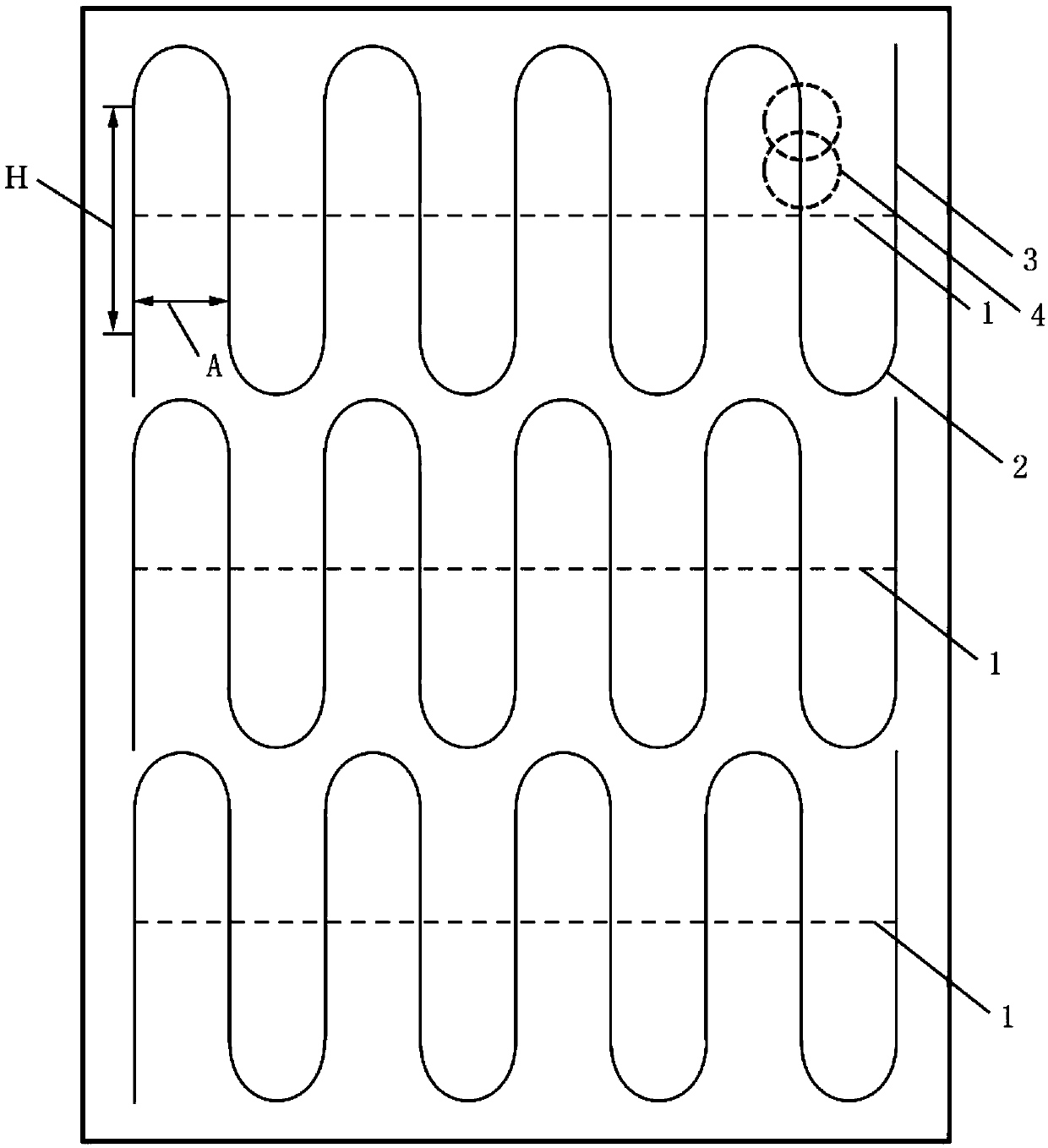
[0026] A laser scanning path planning method for additively manufacturing three-dimensional objects of the present invention, the specific operation process includes the following steps, such as figure 2 Shown:

[0027] Step 1. Input the slice files of each layer of the part model;

[0028] Step 2. Determine the partition reference line according to the structural characteristics of the part and user settings, and partition the slices of each layer of the part;

[0029] The specific process of step 2 is as follows:

[0030] Step 2.1 Read in the height H of the straight line segment 3 in the serpentine path set by the user, the radius R of the arc segment 2, the scanning distance A and the diameter D of the spot 4; among them,

[0031] Step 2.2 Determine the position of the reference line 1 of each partition according to the structural c...


PUM


Abstract

The invention discloses a laser scanning path planning used for additive-manufacturing a three-dimensional object. The laser scanning path planning method comprises the following steps: firstly, inputting each layer of slice files of a part model; then, determining a partition datum line according to structural features of a part and user settings, and partitioning each layer of slices of the part; and finally, performing S-shaped scanning planning in each partition, wherein an S-shaped scanning path comprises a datum line, a circular-arc section and a linear section. According to the method disclosed by the invention, S-shaped scanning path planning is performed on sliced files, heat input can be improved in a scanning process, relatively high energy is kept, and the forming quality problem due to the fact that burning loss is caused as thermal stress is too great or scanning speed is low while cold speed is too high during great-width and large-light-spot part processing can be effectively solved. While part quality is improved, skip reduction is realized through circular-arc oscillation, so that the service life of a laser unit is prolonged.

Description

technical field [0001] The invention belongs to the technical field of additive manufacturing, and relates to a laser scanning path planning method for additive manufacturing of three-dimensional objects. Background technique [0002] Additive manufacturing technology is based on three-dimensional CAD model data, by adding materials and manufacturing them layer by layer. It is based on the computer three-dimensional design model, through the software layered discrete and numerical control forming system, the material is piled up layer by layer with high-energy beams, and finally superimposed and formed to manufacture physical products. [0003] There are many methods of additive manufacturing, which are mainly divided into manufacturing methods based on powder feeding methods and powder spreading methods. The manufacturing method based on the powder spreading method includes the selective laser melting technology. The processing process is as follows: first design the three...

Claims


Application Information

Patent Timeline
Patent Type & Authority Applications(China)
IPC IPC(8): B22F3/105B33Y10/00B33Y50/02
CPCB33Y10/00B33Y50/02B22F10/00B22F10/36B22F10/366B22F10/28Y02P10/25
Inventor 杨东辉王婵
Owner XIAN BRIGHT ADDTIVE TECH CO LTD
Why Eureka
Try Eureka