Drilling equipment for electronic device machining

A technology of drilling equipment and electronic devices, applied in metal processing equipment, drilling/drilling equipment, boring/drilling and other directions, can solve the problem of insignificant processing efficiency of the shell, and achieve a simplified drilling process and a simple structure. , the effect of improving processing efficiency

Inactive Publication Date: 2019-04-19
广安职业技术学院
View PDF8 Cites 1 Cited by
  • Summary
  • Abstract
  • Description
  • Claims
  • Application Information

AI Technical Summary

Problems solved by technology

[0004] However, this device is only suitable for circuit boards, and the processing efficiency for the housing of electronic devices is not significant

Method used


Image

  • Drilling equipment for electronic device machining
  • Drilling equipment for electronic device machining
  • Drilling equipment for electronic device machining

Examples


Embodiment 1

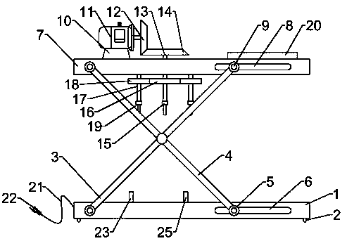
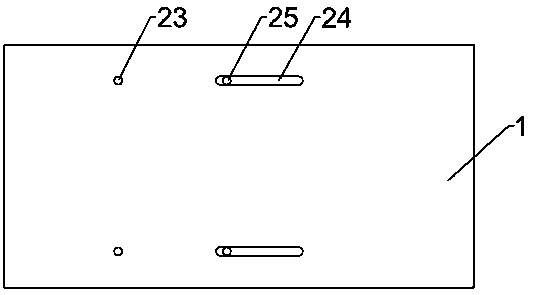
[0021] Example 1: Please refer to Figure 1-3 , a drilling device for processing electronic devices, including a processing base plate 1, the left side of the processing base plate 1 is connected with a first rotating rod 3 symmetrically rotated forward and backward, and the middle part of the first rotating rod 3 is hinged with a second rotating rod 4 of equal length The lower end of the second rotating rod 4 is rotatably connected with the first limit sliding rod 5, and the bottom right side of the processing base plate 1 is provided with the first limit chute 6, and the first limit sliding rod 5 is slidably connected with the first limit chute 6, The top of the second rotating rod 4 is rotatably connected to the top plate 7, and the right side of the top plate 7 is provided with a second limit chute 8, and the top of the first rotating rod 3 is rotatably connected with a second limit slide bar 9, and the second limit slide bar 9 is connected to the second limit slide bar 9. ...

Embodiment 2

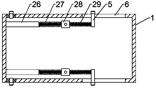
[0033] Embodiment 2: This embodiment is a further improvement of the previous embodiment: the stiffness coefficient of the first spring 27 is smaller than the stiffness coefficient of the second spring 29. At this time, when the first spring 27 and the second spring 29 are stretched, The stretched length of the first spring 27 is greater than that of the second spring 29, so as to ensure that the workpiece to be drilled is positioned first, and then the drilling operation is performed.

[0034] The working principle of the present invention is: when in use, the device is energized, and then the motor 11 can be turned on, the rotation of the motor 11 drives the driving bevel gear 12 to rotate, and then drives the driven bevel gear 14 to rotate, and the rotation of the driven bevel gear 14 can drive the first A drill bit 15 rotates, and the driving gear 16 drives the driven gear 18 to rotate simultaneously, so that the second drill bit 19 rotates synchronously, and can drill a pl...


PUM


Abstract

The invention discloses drilling equipment for electronic device machining, and relates to drilling equipment. A machining bottom plate is included. A first rotation rod is rotationally connected to the left side of the machining bottom plate in a front-back symmetry manner. An equal-length second rotation rod is hinged to the middle portion of the first rotation rod. The lower end of the second rotation rod is rotationally with a first limiting sliding rod. A first limiting sliding groove is formed in the right side of the lower portion of the machining bottom plate and is in sliding connection with the first limiting sliding rod. A top plate is rotationally connected to the top of the second rotation rod. A second limiting sliding groove is formed in the right side of the top plate. Thetop of the first rotation rod is rotationally connected with a second limiting sliding rod which is in sliding connection with the second limiting sliding groove. The drilling equipment is simple in structure and convenient to use; during usage, the drilling process can be simplified, drilling can be conducted without accurate manual device positioning; the device drives a drill bit to descend fordrilling through downward pressing of the top plate, an electronic device is accurately positioned in the top plate descending process, and the drilling efficiency is effectively improved.

Description

technical field [0001] The invention relates to a drilling device, in particular to a drilling device used for processing electronic devices. Background technique [0002] Drilling refers to the operation of machining a hole in a solid material with a drill. There are many devices that need to be drilled in electronic devices, especially the housing of electronic equipment that needs to be drilled. Since most of the structures are hollow, when positioning, you only need to clamp one side on the positioning block, and then apply force to the other side to prevent the device from sliding. [0003] Chinese patent (authorized announcement number: CN208195721U) discloses a drilling device for circuit board production, including a drilling mechanism, a limit device and a control device. The drilling mechanism includes a drill and is used to drive the drill in three dimensions. The drive mechanism that moves in the space, the drill bit is arranged directly above the limit device,...

Claims


Application Information

Patent Timeline
Patent Type & Authority Applications(China)
IPC IPC(8): B23B39/16B23B47/26B23Q3/06
CPCB23B39/162B23B47/26B23Q3/06
Inventor 任银广杜柯毛金凤
Owner 广安职业技术学院
Why Eureka
Try Eureka