
Flue gas distributor

A distributor and flue gas technology, which is applied in chemical instruments and methods, special treatment targets, water/sewage treatment, etc., can solve the problem of uneven mixing of flue gas and atomized wastewater, and it is not suitable for bypass evaporation of power plant wastewater , impact and other issues

Pending Publication Date: 2019-04-19
ZHEJIANG ZHENENG TECHN RES INST
View PDF0 Cites 2 Cited by
  • Summary
  • Abstract
  • Description
  • Claims
  • Application Information

AI Technical Summary

Problems solved by technology

[0003] The technical problem to be solved and the technical task proposed by the present invention are to overcome the fact that the existing flue gas distributor is not suitable for bypass evaporation of power plant wastewater, the uneven mixing effect of flue gas and atomized wastewater is poor, and the entrainment and corrosion contact of atomized wastewater occurs. The metal components affect the safety and reliability of the equipment. The invention provides a flue gas distributor. The flue gas distributor can make the hot flue gas swirl flow into the evaporation tower and fully and uniformly mix with the atomized waste water. To enhance the effect of evaporating waste water, effectively inhibit the entrainment of waste water, avoid equipment corrosion, and improve the safety and reliability of equipment operation

Method used


Image

  • Flue gas distributor
  • Flue gas distributor

Examples


Embodiment Construction

[0016] The present invention will be further described below in conjunction with the accompanying drawings and specific embodiments.

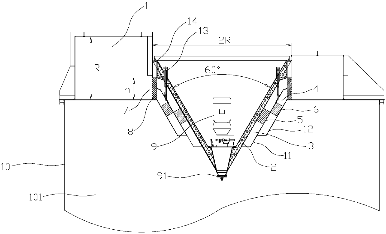
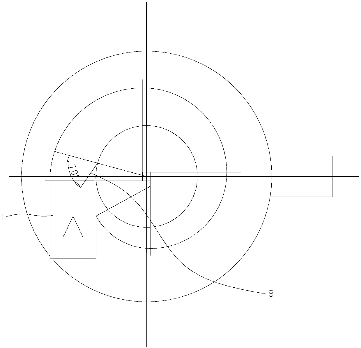
[0017] Such as figure 1 As shown, a flue gas distributor includes a volute-shaped equal pressure air chamber 1 arranged on the top of the evaporation tower 10 and a flue gas distributor inside the equal pressure air chamber 1. The entrance of the equal pressure air chamber 1 is sideways. A square with a length of R, the smoke distributor includes a cone-shaped distributor body 2, a double-layer air flow channel surrounding the outside of the distributor body 2, and the diameter of the top surface of the distributor body 2 is 2R. The double-layer airflow channel is composed of an inner layer annular airflow channel 3 and an outer layer annular airflow channel 4 with a tapered cross-section and are mutually isolated, the upper and lower ends of the inner layer annular airflow channel 3 and the outer layer annular airflow channel 4 Open, the inne...


PUM


Abstract

The invention relates to the field of wastewater drying equipment, in particular to a flue gas distributor for waste water flue gas bypass evaporation. The existing flue gas distributor is not suitable for power plant wastewater bypass evaporation. There are some problems, such as poor mixing effect of flue gas and atomized wastewater, entrainment of wastewater and corrosion of equipments, and soon. The invention provides a flue gas distributor, comprising an isobaric air chamber which is arranged in a volute shape at the top of the steaming tower and a flue gas distributor on the inner sideof the isostatic air chamber. The flue gas distributor comprises a distributor body, a double-layer airflow passage around the outside of the distributor body. Inner and outer air guiding blades are arranged in the double-layer annular airflow passage. A circular flue gas outlet docking double-layer airflow passage is arranged on the inner side of the isobaric air chamber. An outlet guide vane tangentially directed to the swirling direction of the flue gas in the equal pressure chamber is circumferentially arranged in the annular flue gas outlet. An atomizer with an atomizing disk is arrangedin the inner cavity of the distributor body. According to the invention, the hot flue gas swirling flow can be sent into the steaming tower and uniformly mixed with the atomized wastewater, and at thesame time the water entrainment is inhibited to avoid equipment corrosion.

Description

technical field [0001] The invention relates to the field of waste water drying equipment, in particular to a flue gas distributor used for waste water flue gas bypass evaporation. Background technique [0002] At present, the environmental protection transformation of many thermal power plants requires zero discharge of wastewater, which requires drying treatment of high-salt wastewater at the end. The current mainstream drying treatment method is wastewater bypass evaporation technology, which mainly sprays wastewater into the wastewater evaporation tower through a centrifugal atomizer, and then exchanges heat with the hot flue gas that is rotated into the wastewater evaporation tower Change the quality to achieve the purpose of evaporating to dryness. The hot flue gas drawn from the bypass pipe of the tail flue needs to be re-distributed reasonably and evenly before entering the waste water evaporation tower, so as to fully mix and contact with the atomized waste water, ...

Claims


Application Information

Patent Timeline
Patent Type & Authority Applications(China)
IPC IPC(8): C02F1/16
CPCC02F1/16C02F2303/10
Inventor 陈彪陈雨帆祁志福刘春红王文欣吴贤豪
Owner ZHEJIANG ZHENENG TECHN RES INST
Learn More