Industrial boiler adopting flue gas recirculation and with staggered SNCR and OFA
A technology of flue gas recirculation and staggered arrangement, which is applied in the combustion of lump fuel and gaseous fuel, the combustion of liquid fuel and gaseous fuel, the combustion of gaseous fuel and powder fuel, etc. Complete and high NOx emissions
- Summary
- Abstract
- Description
- Claims
- Application Information
AI Technical Summary
Problems solved by technology
Method used
Image
Examples
specific Embodiment approach 1
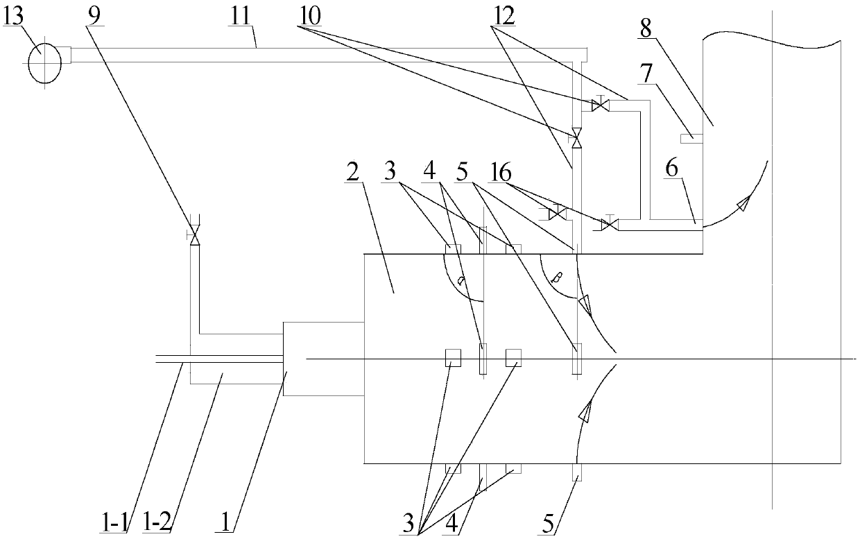
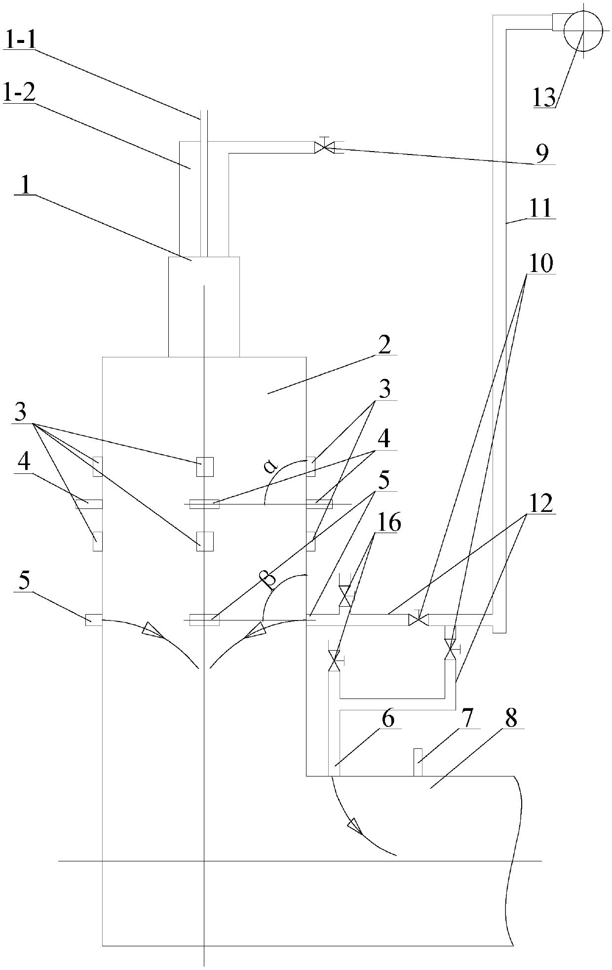
[0022] Specific implementation mode one: combine figure 1 and figure 2 Describe this embodiment, the industrial boiler adopting flue gas recirculation SNCR and OFA staggered arrangement described in this embodiment, it includes a burner 1, a furnace 2, a temperature sensor 3, a primary reducing agent nozzle 4, a primary burn-off air Nozzle 5, secondary overburning air nozzle 6, secondary reducing agent nozzle 7, upward flue 8, secondary air pipe valve 9 and flue gas recirculation system, burner 1 is arranged on the front wall of furnace 2, and primary The reducing agent nozzle 4, the temperature sensor 3, and the primary overfired air nozzle 5 are sequentially arranged on the outer wall of the furnace 2 along the flue gas flow direction. The inlet of the exhaust air nozzle 6 is connected, the secondary air air pipe valve 9 is installed on the inlet of the burner secondary air duct 1-2, the upward flue 8 is connected with the furnace 2, the secondary exhaust air nozzle 6, and...
specific Embodiment approach 2
[0025] Specific implementation mode two: combination figure 1 and figure 2 To illustrate this embodiment, the flue gas recirculation system of an industrial boiler using flue gas recirculation SNCR and OFA staggered arrangement in this embodiment includes a recirculation flue gas pipeline valve 10, a recirculation flue gas pipeline 11, a recirculation flue gas The branch pipe 12, the recirculation fan 13 and the overfired air pipe valve 16, the outlet of the recirculated flue gas pipe 11 passes through the recirculated flue gas branch pipe 12 and the inlet of the primary overburned air nozzle 5 and the secondary overfired air nozzle 6 Connection, the recirculation gas pipeline valve 10 and the overfired air pipeline valve 16 are installed on the recirculation flue gas branch pipeline 12 . The amount of flue gas sent into the overfired air pipeline is adjusted through the recirculation flue gas pipeline valve 10 and the overfired air pipeline valve 16 . Other components and ...
specific Embodiment approach 3
[0026] Specific implementation mode three: combination figure 1 and figure 2To illustrate this embodiment, the burner 1 of the industrial boiler adopting flue gas recirculation SNCR and OFA staggered arrangement in this embodiment includes a primary air duct 1-1 and a secondary air duct 1-2, and the secondary air duct 1- 2 is arranged outside the primary air duct 1-1, the primary air duct 1-1 and the secondary air duct 1-2 are arranged coaxially, and their axis is perpendicular to the front wall of the furnace 2. The outlet of the recirculation flue gas pipe 11 is respectively connected with the entrances of the secondary air duct 1-2, the primary overburning air nozzle 5 and the secondary overburning air nozzle 6 through the recirculating flue gas branch pipe 12, and the recirculating flue gas branch Pipes 12 are provided with recirculation flue gas pipe valves 10 to adjust the amount of flue gas sent into each pipe. Other components and connections are the same as those i...
PUM
 Abstract
Description
Claims
Application Information
 - R&D
- Intellectual Property
- Life Sciences
- Materials
- Tech Scout
- Unparalleled Data Quality
- Higher Quality Content
- 60% Fewer Hallucinations
Browse by: Latest US Patents, China's latest patents, Technical Efficacy Thesaurus, Application Domain, Technology Topic, Popular Technical Reports.
© 2025 PatSnap. All rights reserved.Legal|Privacy policy|Modern Slavery Act Transparency Statement|Sitemap|About US| Contact US: help@patsnap.com


