Impact test device and method used for rock or concrete test sample

A technology for concrete specimens and impact tests, which is applied in the direction of measuring devices, instruments, scientific instruments, etc., can solve problems such as the inability to study the impact characteristics of secondary ejection characteristics, the inability to accurately control the impact velocity, etc., to achieve simple and convenient assembly, Reduced hazards, highly reproducible results

Inactive Publication Date: 2019-04-19
WUHAN UNIV
View PDF6 Cites 16 Cited by
  • Summary
  • Abstract
  • Description
  • Claims
  • Application Information

AI Technical Summary

Problems solved by technology

[0003] Hopkinson bar test technology is currently the most important and reliable test method for studying the mechanical properties of materials at high strain rates, and is an important part of explosion and impact dynamics test technology; if the existing Hopkinson bar test technology is used to study The dynamic impact characteristics of concrete and rock, although the dynamic mechanical properties of concrete and rock can be studied, but this test technology cannot accurately control the impact velocity, and the test specimen is limited by the output rod, so it is impossible to study the secondary ejection characteristics and the impact on different impact objects Characteristic research; therefore, it is necessary to design a test device that uses the test specimen as an active impact object, and use 3DDIC (3Dimension Digital ImageCorrelation) software to analyze the impact of the specimen under the condition that the impact velocity of the specimen can be precisely controlled and secondary ejection occurs Instantaneous stress and strain field

Method used


Image

  • Impact test device and method used for rock or concrete test sample
  • Impact test device and method used for rock or concrete test sample
  • Impact test device and method used for rock or concrete test sample

Examples


Embodiment Construction

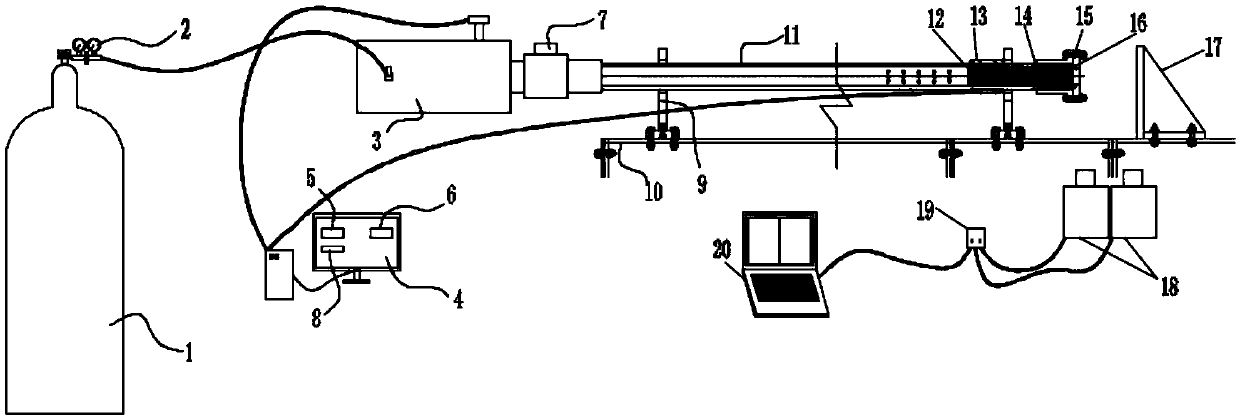
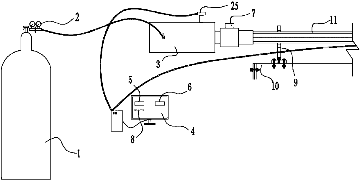
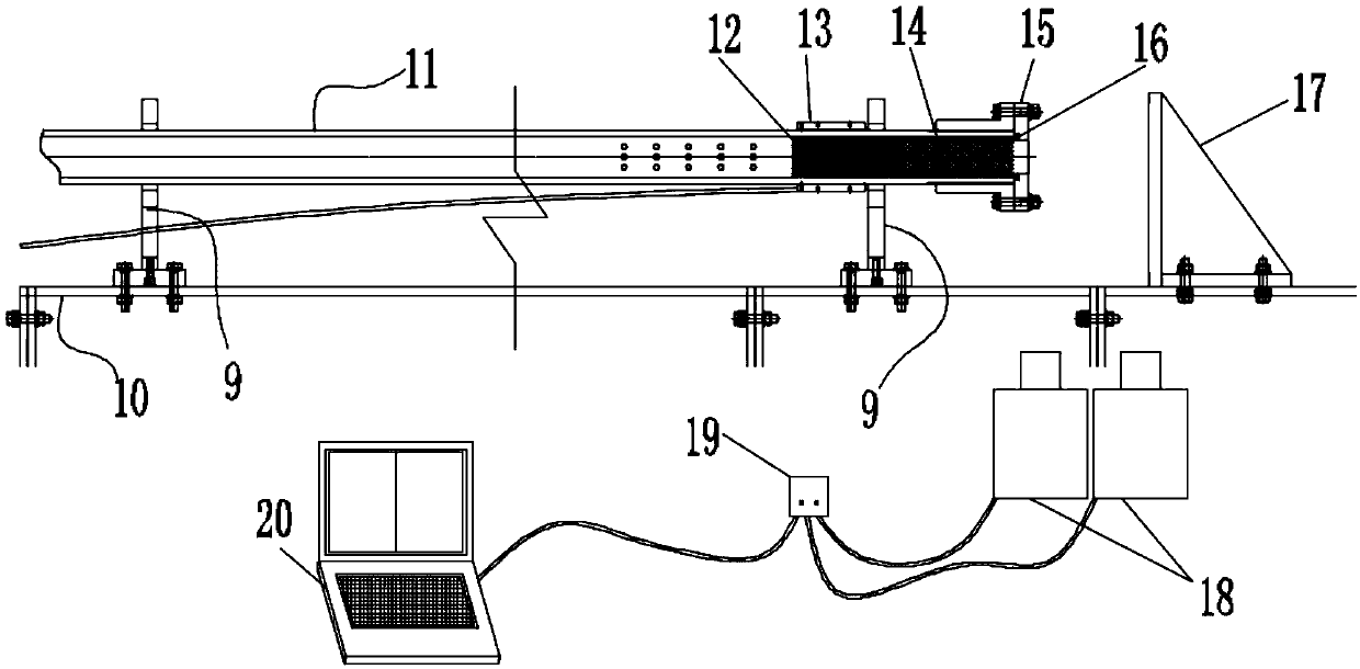
[0038] The present invention will be further described below in conjunction with the accompanying drawings and specific embodiments.

[0039] The device of the present invention is mainly used to explore the dynamic impact characteristics (fracture characteristics and secondary ejection situation) of concrete and rock test pieces and the impact test device of the stress and strain situation at the moment of impact, mainly comprising PC control computer 4, launch system, fixed Support, electronic laser velocimeter 13, high-speed camera 18 shooting system and test piece baffle 17, described fixed support is used for fixing launch system, and test piece baffle is set relative to launch system, and promptly described test piece baffle 17 is located at At the exit of the launch system, the electronic laser velocimeter 13 is located at the exit end of the launch system to detect the speed of launching rocks or concrete samples, and the high-speed camera 18 shooting system is located ...


PUM


Abstract

The invention discloses an impact test device and method used for a rock or concrete test sample. The impact test device comprises a launching system, a fixing support, an electronic laser velocimeter, a high-speed camera shooting system and a test sample baffle, the test sample baffle and the launching system are arranged oppositely, and the electronic laser velocimeter is used for detecting thespeed of the launched test sample; the launching system comprises a nitrogen steel cylinder, a gas storage room, a launching barrel, a sabot and a sabot and test sample separating device, and the gasstorage room is connected with the launching barrel through an electromagnetic switch. During usage, the gas storage room is filled with gas through the nitrogen steel cylinder, then the electromagnetic switch is rapid switched on, gas flows push the sabot with the test sample to conduct launching rapidly from the launching barrel, then, the test sample and the sabot are separated, the test sampleimpacts on the test sample baffle, impact data of the test sample is recorded through the electronic laser velocimter and the high-speed camera shooting system, and the transient stress strain fieldof the test sample impact is analyzed through 3DDIC software. The test device is easy and convenient to assemble, efficient in test process and high in repeatability.

Description

technical field [0001] The invention belongs to the field of impact tests, and in particular relates to an impact test device and test method for rock or concrete specimens, which are used to study the dynamic impact characteristics of concrete and rocks (fracture characteristics and secondary ejection conditions) and use 3DDIC (3Dimension Digital Image Correlation) software to analyze the stress-strain field analysis of the specimen at the moment of impact. Background technique [0002] Concrete and rock are the most commonly used materials in human engineering activities. Many man-made, natural disasters and engineering accidents are closely related to their dynamic impact characteristics; for example, with the rapid development of the world economy and industry, the demand for energy and transportation Blasting and rockburst in mining and tunnel construction will be inevitable. Under the action of strong explosion impact load, the splashed rock fragments will obtain extre...

Claims


Application Information

Patent Timeline
Patent Type & Authority Applications(China)
IPC IPC(8): G01N3/307
CPCG01N3/307
Inventor 吴志军刘洋刘泉声张波翁磊马亮亮于方正
Owner WUHAN UNIV
Why Eureka
Try Eureka