
Static evaporation pressure-hold test device and method for vehicular LNG (liquefied natural gas) cylinders

A testing device and evaporation rate technology, applied in the direction of analyzing materials, instruments, etc., can solve the problems that the operator's safety cannot be guaranteed, the real data cannot be obtained, and the data error is large, so as to avoid the risk of overpressure, save the assembly time, Real and accurate effect of flow value

Pending Publication Date: 2019-04-19
WUHAN BOILER PRESSURE VESSEL INSPECTION INST
View PDF0 Cites 2 Cited by
  • Summary
  • Abstract
  • Description
  • Claims
  • Application Information

AI Technical Summary

Problems solved by technology

[0005] 1. During the test, the above components need to be assembled on the pipeline of the gas cylinder in sequence. The assembly time is long and the airtightness is poor after repeated disassembly and assembly; 2. There is a heating device behind the pressure controller without a pressure gauge, and the pressure controller has pressure After that, it is not necessarily normal pressure, and the volume expansion is caused by the temperature difference caused by the temperature rise. The volume density of the evaporation volume of the medium under the pressure environment before the pressure controller changes after the pressure controller, so the recorded flow value is distorted, resulting in The measured data has a large error; 3. After the measurement, the whole set of equipment contains high pressure, and there is no pressure relief measure. The disassembly process is operated under pressure, and the safety of the operator cannot be guaranteed; 4. Only a single pressure is changed, not changed Other parameters, and under different pressure conditions, the physical parameters of the medium are very different, such as calculating α according to the original formula 20 Can't get real data

Method used


Image

  • Static evaporation pressure-hold test device and method for vehicular LNG (liquefied natural gas) cylinders
  • Static evaporation pressure-hold test device and method for vehicular LNG (liquefied natural gas) cylinders
  • Static evaporation pressure-hold test device and method for vehicular LNG (liquefied natural gas) cylinders

Examples


Embodiment Construction

[0035] The following specific examples illustrate the present invention in further detail.

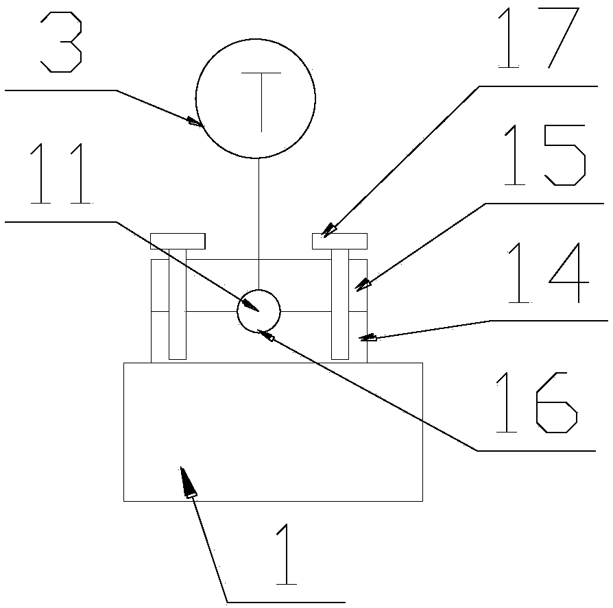
[0036] like Figure 1-2 As shown, a kind of vehicle LNG cylinder static evaporation rate pressure-holding test device provided by the present invention comprises a base 1, a test tube is arranged on the base 1, the front end of the test tube is connected with the vent pipe 19 of the checked bottle 18, and the rear The end of the test tube is connected with the gas recovery pipeline. The test tube is equipped with a temperature riser 2, a thermometer 3, a pressure gauge 4, a flow meter 7, and a micro-opening safety valve 8. There are pressure gauges 4 and 7 flow meters on the test tube. Equipped with a fully opened safety valve 5 and a vent stop valve 6 .

[0037]The test tube includes a first metal tube 11, a second metal tube 12, and a third metal tube 13 from front to back. The front and rear ends of the second metal tube 12 are detachable from the first metal tube 11 and the third ...


PUM


Abstract

The invention discloses a static evaporation pressure-hold test device for vehicular LNG (liquefied natural gas) cylinders, which is characterized by comprising a base; a test tube is arranged on thebase; the front end of the test tube is connected with an emptying tube of a cylinder under test; the rear end of the test tube is connected with a gas recycling line; a heater, a thermometer, a pressure meter, a flowmeter and a low-lift safety valve are arranged on the test tube sequentially from front to rear; a full-lift safety valve and an emptying stop valve are arranged on the test tube between the pressure meter and the flowmeter. The whole device herein is directly connected with a heat-insulating cylinder line; connecting the components sequentially to the cylinder line as in the prior art is not required; assembly time is saved, and it is avoided that multiple assembly and disassembly affects airtightness between the components.

Description

technical field [0001] The invention relates to a static evaporation rate test of an insulating gas cylinder, in particular to a static evaporation rate test device and a test method for a vehicle-used LNG gas cylinder. Background technique [0002] With the release and implementation of GB / T 34347-2017 "Periodic Inspection and Evaluation of Cryogenic Insulated Gas Cylinders", there is a relatively unified method for the periodic inspection of LNG cylinders for vehicles nationwide. In this standard, the non-disassembly method has been allowed for the inspection of LNG cylinders for vehicles, and the inspection test is directly based on the LNG medium. The test device is to install a vent pipe valve, a temperature riser, a thermometer, and a gas mass flow meter in sequence on the vent pipe of the tested part. The test process is as follows: After filling the adiabatic cylinder with liquid, stand still for at least 48 hours, open the vent valve during the period of rest → con...

Claims


Application Information

Patent Timeline
Patent Type & Authority Applications(China)
IPC IPC(8): G01N7/00
CPCG01N7/00Y02T10/30
Inventor 刘彪黄璞李晓东
Owner WUHAN BOILER PRESSURE VESSEL INSPECTION INST
Learn More