Wavelength offset correction method and device and computer device

A technology of wavelength shift and correction method, which is applied in the field of spectral analysis, can solve problems such as irreversible, slight shift of spectral position, deviation of actual spectral position, etc., and achieve a wide range of applications

Active Publication Date: 2019-04-19
浙江全世科技有限公司
View PDF3 Cites 2 Cited by
  • Summary
  • Abstract
  • Description
  • Claims
  • Application Information

AI Technical Summary

Problems solved by technology

Among them, the temperature control method of the optical chamber: when the external temperature changes, the temperature distribution of the optical chamber will still change, and the spectral position will still drift slightly, which cannot be eradicated, and cannot be solved due to mechanical vibration and mechanical stress deformation. The wavelength shift problem caused by the mechanical backhaul difference
Light source calibration method: It needs to be performed regularly with the help of external or built-in calibration light sources (neon lamp, mercury lamp, xenon lamp or argon lamp). Generally, it also needs to cooperate with the peak-finding algorithm. Using an e

Method used


Image

  • Wavelength offset correction method and device and computer device
  • Wavelength offset correction method and device and computer device
  • Wavelength offset correction method and device and computer device

Examples


Embodiment 1

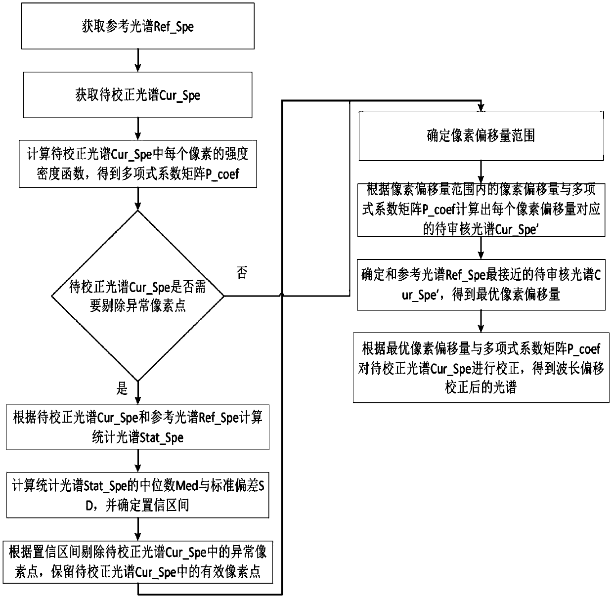
[0061] see figure 1 , a wavelength offset correction method, comprising:

[0062] Obtain the reference spectrum Ref_Spe and the spectrum to be corrected Cur_Spe;

[0063] Calculate the intensity density function of each pixel in the spectrum Cur_Spe to be corrected to obtain the polynomial coefficient matrix P_coef, and each group of polynomial coefficients in the polynomial coefficient matrix P_coef is the coefficient of the intensity density function of a pixel in the spectrum Cur_Spe to be corrected;

[0064] Determine the pixel offset range;

[0065] Calculate the spectrum Cur_Spe' corresponding to each pixel offset according to the pixel offset within the pixel offset range and the polynomial coefficient matrix P_coef;

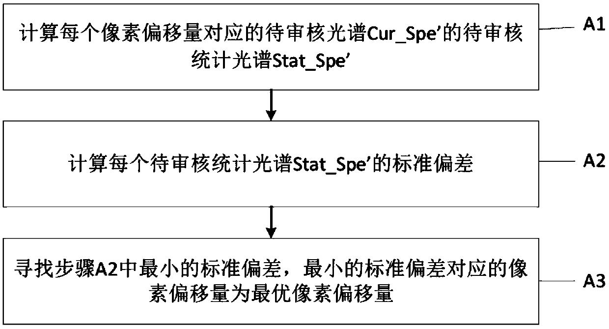
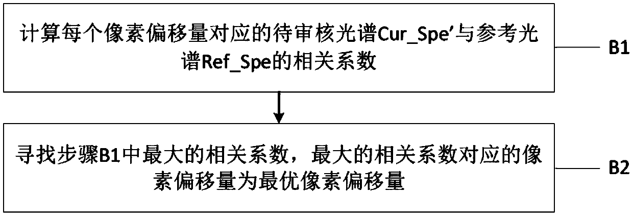
[0066] Determine the spectrum Cur_Spe' that is closest to the reference spectrum Ref_Spe to obtain the optimal pixel offset;

[0067] The spectrum to be corrected Cur_Spe is corrected according to the optimal pixel offset and the polynomial coefficient...

Embodiment 2

[0142] see Figure 12 , the present invention also discloses a wavelength offset correction device, comprising:

[0143] Obtaining module, used for obtaining reference spectrum Ref_Spe and spectrum Cur_Spe to be corrected;

[0144] The first calculation module is used to calculate the intensity density function of each pixel in the spectrum Cur_Spe to be corrected to obtain the polynomial coefficient matrix P_coef, and each group of polynomial coefficients in the polynomial coefficient matrix P_coef is respectively the intensity of a pixel in the spectrum Cur_Spe to be corrected coefficient of the density function;

[0145] The second calculation module is used to calculate the pixel offset within the pixel offset range and the polynomial coefficient matrix P_coef to calculate the spectrum Cur_Spe' corresponding to each pixel offset according to the pixel offset range; and determine and refer to The spectrum Ref_Spe is closest to the spectrum Cur_Spe' to be reviewed, and the...

Embodiment 3

[0159] The invention also discloses a computer device, which includes a memory, a processor, and a computer program stored in the memory and operable on the processor. When the processor executes the computer program, the above wavelength offset correction method is realized.


PUM


Abstract

The invention discloses a wavelength offset correction method, which comprises the following steps of: acquiring a reference spectrum and a spectrum to be corrected; calculating an intensity density function of each pixel in the spectrum to be corrected to obtain a polynomial coefficient matrix, wherein each group of polynomial coefficients in the polynomial coefficient matrix are coefficients ofthe intensity density function of one pixel in the spectrum to be corrected respectively; determining a pixel offset range; calculating a spectrum to be audited corresponding to each pixel offset according to the pixel offset in the pixel offset range and the polynomial coefficient matrix; determining the spectrum to be audited which is closest to the reference spectrum to obtain the optimal pixeloffset; correcting the spectrum to be corrected according to the optimal pixel offset and the polynomial coefficient matrix to obtain the spectrum after wavelength offset correction. The wavelength offset correction method can correct the non-integer multiple pixel offset of the spectral data without depending on a peak finding method. The method also discloses a wavelength offset correction device and a computer device.

Description

technical field [0001] The invention belongs to the field of spectrum analysis, and in particular relates to a wavelength offset correction method and device and computer equipment. Background technique [0002] The micro fiber optic spectrometer uses a linear array detector to convert the optical signal into an electrical signal, and the echelle grating uses an area array detector to convert the optical signal into an electrical signal. During the use of these full-spectrum direct-reading spectrometers, the temperature, humidity, vacuum degree, mechanical vibration, and mechanical stress deformation of the optical chamber will affect the optical path structure, resulting in small changes in the relative position of the spectrum and the linear array detector, which is expressed as a specific wavelength. The pixel on the linear array detector is shifted, that is, the spectral position changes; for the sequential scanning spectrometer, since the stepping motor needs to be used...

Claims


Application Information

Patent Timeline
IPC IPC(8): G01N21/27G06F17/16
CPCG06F17/16G01N21/274
Inventor 于丙文陈挺常红旭郑磊落刘文龙冯雨晨方博凡
Owner 浙江全世科技有限公司
Why Eureka
Try Eureka