System and method for optical spectrum fast peak reporting

a technology of optical spectrum and reporting system, applied in the field of system and method for fast peak reporting of optical spectrum, can solve the problem of long-haul wdm system waiting, and achieve the effect of fast peak finding and quick finding some information

Inactive Publication Date: 2006-07-04
EXCELITAS TECH
View PDF11 Cites 0 Cited by
  • Summary
  • Abstract
  • Description
  • Claims
  • Application Information

AI Technical Summary

Problems solved by technology

As a result, some long haul WDM systems can wait for over a second to obtain some types of information.

Method used


Image

  • System and method for optical spectrum fast peak reporting
  • System and method for optical spectrum fast peak reporting
  • System and method for optical spectrum fast peak reporting

Examples


Embodiment Construction

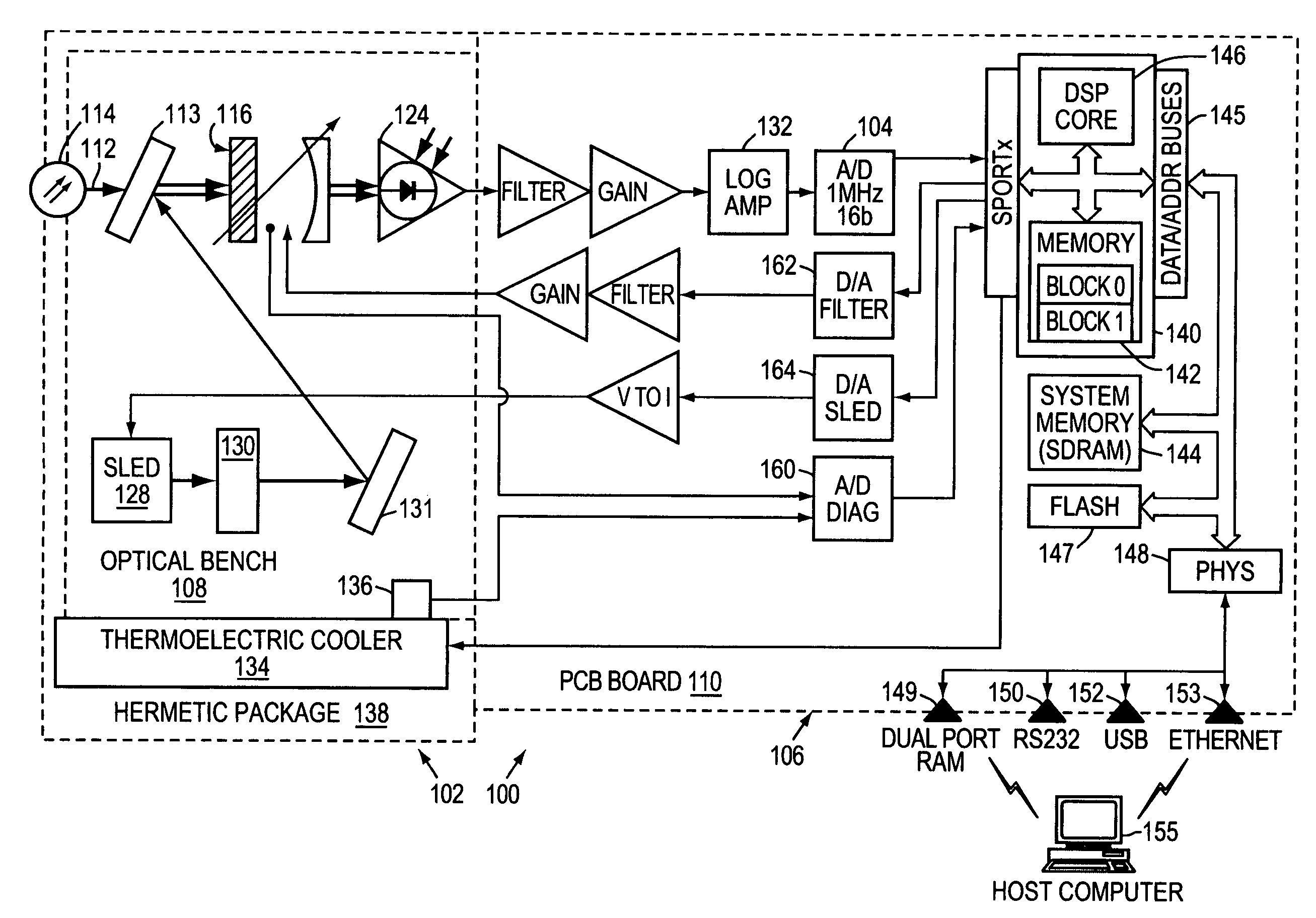
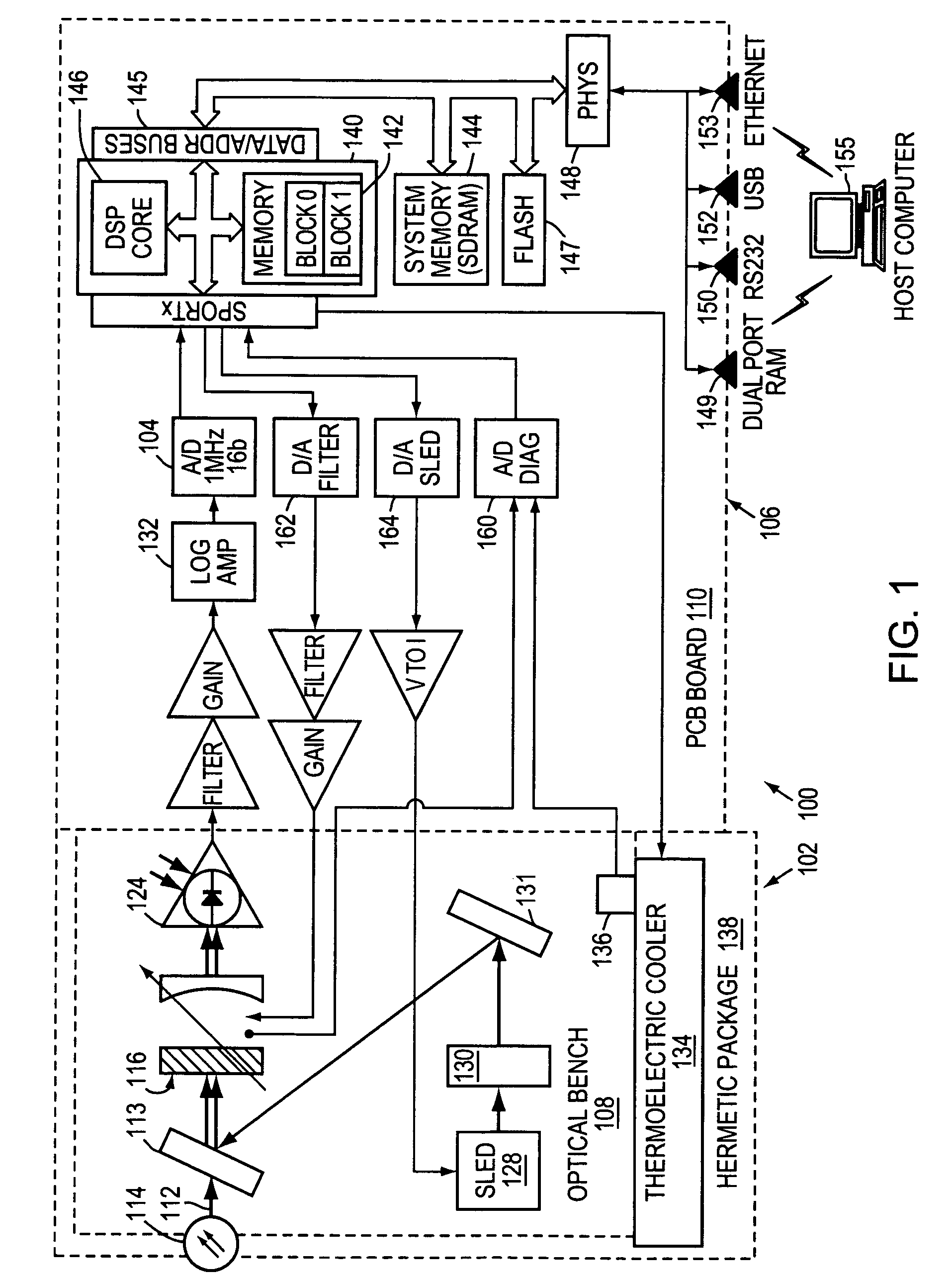
[0022]FIG. 1 shows an optical spectrum monitoring system 100, which has been constructed according to the principles of the present invention.

[0023]In more detail, the system 100 generally comprises a spectrum detection subsystem 102, an analog to digital converter 104, and a data processing subsystem 106. Generally, the spectrum detection subsystem 102 is assembled on a substrate or optical bench 108; and the data processing subsystem 106 is interconnected on a printed circuit board 110, in a current implementation.

[0024]In the illustrated example, the spectrum detection subsystem 102 is a microelectromechanical system (MEMS) implementation. Specifically, an input optical signal 112, which is supplied by an optical fiber 114 for example, is received onto the optical bench 108 and transmitted to a MEMS tunable filter 116, typically through collimation, focusing optics if required.

[0025]In other embodiments, fiber grating-based systems are used in place of the MEMS filter 116.

[0026]F...


PUM

PropertyMeasurementUnit
optical spectrum monitoringaaaaaaaaaa
temperatureaaaaaaaaaa
spectrumaaaaaaaaaa

Abstract

A system and method for fast peak finding in an optical spectrum prioritizes the information it first generates and how the information is then forwarded from the system to a host computer, for example. A spectrum detection subsystem generates a spectrum of an optical signal. An analog-to-digital converter converts the spectrum into sample data. Finally, a data processing subsystem first detects the spectral locations of peaks in the spectrum using the sample data and then uploads the peak information to a host computer before performing processing to determine the shapes of the peaks and / or noise information for the optical signal, for example. The system is thus able to quickly find some information, such as whether or not channels or carriers are present, at what frequency the carriers are operating, and the carriers' power level, and send this information to the host computer. In contrast, information concerning spectral shape or the noise floor sent later in time.

Description

RELATED APPLICATIONS[0001]This application is a continuation of application Ser. No. 10 / 644,498 filed on Aug. 20, 2003, which is a divisional of application Ser. No. 10 / 005,712 filed on Nov. 8, 2001, U.S. Pat. No. 6,639,666 both of which are incorporated herein by reference.BACKGROUND OF THE INVENTION[0002]Wavelength division multiplexing (WDM) systems typically comprise multiple, separately modulated, optical carrier signals, each one being assigned to a different channel slot, or frequency, in the WDM signal. The sources for the carriers can be located at a single head-end in long-haul applications or remote from each other, with the channels typically being accumulated onto a single fiber by multiplexers, in metro area network applications, for example. Along the fiber transmission link, the carriers can be regenerated or collectively amplified typically by gain fiber, semiconductor optical amplifiers (SOA), or doped waveguide devices. At the link termination, the carriers are us...

Claims


Application Information

Patent Timeline
Patent Type & Authority Patents(United States)
IPC IPC(8): G01N21/25G01J3/02G01J3/26G01J3/28
CPCG01J3/02G01J3/28G01J3/26G01J3/0264
Inventor LI, YUWHITNEY, PETER S.KORN, JEFFREY A.
Owner EXCELITAS TECH
Why Eureka
Try Eureka