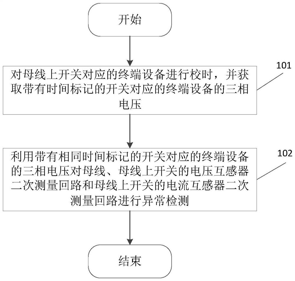
A method and system for abnormal detection of secondary measurement circuits in substations and switching stations
A secondary measurement and anomaly detection technology, which is applied in the direction of measuring electricity, measuring devices, and measuring electrical variables, etc., can solve problems such as wrong phase sequence connection of the secondary circuit of the transformer, insufficient sensitivity of technical means, abnormal data acquisition system, etc., to achieve Effects of improving reliability and sensitivity, ensuring time synchronization, and reducing abnormal loss
- Summary
- Abstract
- Description
- Claims
- Application Information
AI Technical Summary
Problems solved by technology
Method used
Image
Examples
Embodiment 2
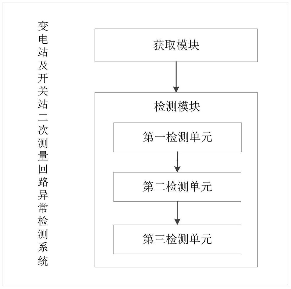
[0090] image 3 It shows a schematic structural diagram of an abnormality detection system for a secondary measurement circuit of a substation and a switchyard according to an embodiment of the present invention, as shown in image 3 As shown, the system may include:
[0091] The acquisition module is used to adjust the time of the terminal equipment corresponding to the switch on the bus, and acquire the three-phase voltage of the terminal equipment corresponding to the switch with the time stamp;
[0092] The detection module is used to use the three-phase voltage of the terminal equipment corresponding to the switch with the same time mark to perform abnormal detection on the busbar, the secondary measurement circuit of the voltage transformer of the switch on the busbar and the secondary measurement circuit of the current transformer of the switch on the busbar .
[0093] Wherein, the time calibration of the terminal equipment corresponding to the switch on the bus may inc...
Embodiment 3
[0124] Figure 4 The main wiring diagram of the single busbar form of the power system switching station showing the abnormal detection method of the secondary measurement circuit of the substation and the switching station according to the embodiment of the present invention, as shown in Figure 4 As shown, the switch KG1 is a loop-in switch, the switch KG2 is a loop-out switch, and the switches KG3~KG6 are feeder switches. The direction of power flows into the bus from the switch KG1, and flows out of the bus from the switches KG2~6.
[0125] An operation and maintenance workstation is configured in the whole system, and a terminal device is respectively installed in the switches KG1~KG6, and the numbers are recorded as ZD1~ZD6. Used to collect their own voltage and current, and then send the voltage and current data to the operation and maintenance workstation, which summarizes all the data, and calculates the effective value of the voltage of each switch, the negative sequ...
PUM
 Abstract
Description
Claims
Application Information
 - R&D
- Intellectual Property
- Life Sciences
- Materials
- Tech Scout
- Unparalleled Data Quality
- Higher Quality Content
- 60% Fewer Hallucinations
Browse by: Latest US Patents, China's latest patents, Technical Efficacy Thesaurus, Application Domain, Technology Topic, Popular Technical Reports.
© 2025 PatSnap. All rights reserved.Legal|Privacy policy|Modern Slavery Act Transparency Statement|Sitemap|About US| Contact US: help@patsnap.com


