Opposite-configuration gear meshing pair based on line-plane conjugation and a design method thereof

A design method and conjugate gear technology, applied in gear transmission, design optimization/simulation, belt/chain/gear, etc., can solve the problem of unresolved gear axis, unresolved gear axis deviation and pitch error, deviation pitch error, etc. question

Pending Publication Date: 2019-04-19
CHONGQING UNIV
View PDF3 Cites 2 Cited by
  • Summary
  • Abstract
  • Description
  • Claims
  • Application Information

AI Technical Summary

Problems solved by technology

[0005] The object of the present invention is to provide a paired gear meshing pair based on line-plane conjugate to solve the problem in the prior art that the line-plane conjugate involute gear transmission is based on the involute, and the tooth profile It has certain limitations and cannot solve the technical problems of gear axis deviation and pitch error
[0006] The pr

Method used


Image

  • Opposite-configuration gear meshing pair based on line-plane conjugation and a design method thereof
  • Opposite-configuration gear meshing pair based on line-plane conjugation and a design method thereof
  • Opposite-configuration gear meshing pair based on line-plane conjugation and a design method thereof

Examples


Embodiment 1

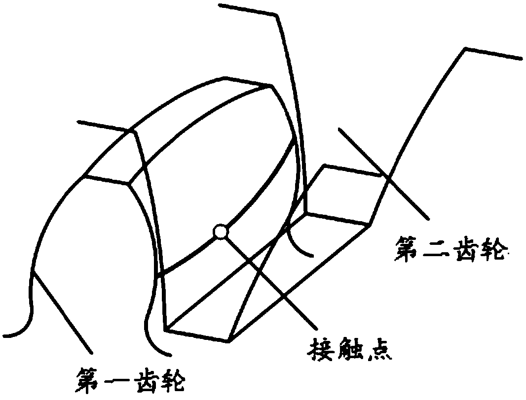
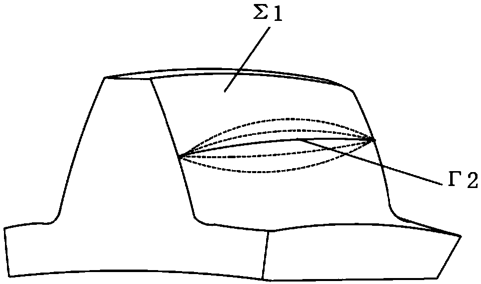
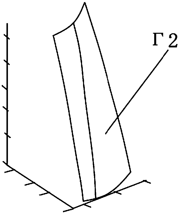
[0067] The present invention provides a method for designing a paired gear meshing pair based on line-plane conjugation. The design method for a paired gear meshing pair based on line-plane conjugate includes the following steps: i) determining the curved surface Σ of the first gear 1 The equation is: Among them, u, v are surface parameters; ii) determine the contact trace on the tooth surface of the first gear The equation is: where φ is a spatial parameter; iii) determine the normal vector of the contact trace on the tooth surface of the first gear (n x2 , n y2 , n z2 )for: iv) by the formula n·v (12) =0, determine the curve and surface ∑ 1 The meshing equation of ; v) according to the contact trace In a fixed coordinate system S 1 The following equation and the meshing equation determine the conjugate curve; vi) According to the conjugate curve, determine the second gear tooth surface Σ 2 equation.

[0068] The present invention takes the internal meshi...

Embodiment 2

[0148] The difference between this embodiment and the first embodiment is that in step vi, the envelope method is used to determine the tooth profile equation of the gear.

[0149] Specifically, as Figure 13 As shown, assume that the gear 2 is fixed, and the instantaneous center line I is purely rolled on the instantaneous center line Π, and the tooth shape 1 forms a curve family on the plane of the gear 2. Since tooth shape 2 and tooth shape 1 are in tangential contact at every instant, mathematically speaking, tooth shape 2 should be the envelope of the curve family formed by tooth shape 1. Using this principle, the tooth shape 2 can be obtained from the motion law of the gear pair and the tooth shape 1. This method is called the envelope method.

[0150] The tooth shape of another gear is enveloped by the tooth shape of one gear. This phenomenon can be clearly observed when the gear is processed by the generating method. For example, the tooth shape of the gear shaping cu...

Embodiment 3

[0152] The difference between this embodiment and the first embodiment is that step vi adopts the tooth profile normal method to determine the tooth profile equation of the gear.

[0153] Specifically, let the gears 1 and 2 both rotate, and at a certain moment, the tooth profile 1 is at Figure 14 The position shown by the solid line in the center, according to the condition of n·v=0, a point M can be obtained on the gear 1, and its normal line passes through the instantaneous center point P, then M is the contact point of the instantaneous tooth profile 1 and 2 . Gear 1 rotates through an angle, and the tooth profile turns to Figure 13 At the position shown by the dotted line in the middle, the point M' where the normal line passes through the point P can also be obtained, and then M' is the contact point of the instantaneous two tooth profiles. Using this method to obtain a series of contact point positions during the rotation of the gear 1, its trajectory in the fixed pl...


PUM


Abstract

The invention provides an opposite-configuration gear meshing pair based on line-plane conjugation and a design method thereof, and relates to the technical field of gear transmission. The transmission mechanism comprises a first gear and a second gear which form a line-plane conjugate gear pair. The line-surface conjugate gear pair comprises a curved surface 1 and a curve 1 which are in continuous tangent contact, the curved surface 1 is located on the first gear, and only one curve on the curved surface 1 is in contact with the curve 1; At the preset moment, the curve 1 keeps point contact with the curved surface 1, and at the preset moment, the contact point of the curve 1 and the curved surface 1 is unique; Wherein the curve 1 is a smooth curve, and the curved surface 1 is a smooth curved surface. The technical problem that in the prior art, a line-plane conjugated involute gear transmission device is established based on an involute, and the tooth shape has certain limitation is solved. The line face-to-face configuration gear has the center distance separability, has the adaptive capacity to the axis deflection error and the pitching error, and is wide in application range.

Description

technical field [0001] The invention relates to the technical field of gear transmission devices, in particular to a paired gear meshing pair based on line-plane conjugation and a design method thereof. Background technique [0002] As a typical mechanical basic part, the gear determines the performance of the equipment to a large extent, so the design of high-performance gear transmission components is also of great significance and engineering practical value. [0003] The most widely used meshing pair of cylindrical gears is the involute gear. The meshing pair of involute gears is surface-to-surface conjugate. The contact between the two surfaces forms a line contact. The tooth shape is involute, and the involute Linear gears have the advantage of separability of the center distance, but they cannot cope with the skew or pitch error of the gear axis, and the gears with linear contact have a high slip rate, which has an adverse effect on the wear of the tooth surface, tran...

Claims


Application Information

Patent Timeline
IPC IPC(8): G06F17/50
CPCG06F30/17G06F30/20F16H55/08F16H1/00
Inventor 陈兵奎张录合彭帅李朝阳安来强
Owner CHONGQING UNIV
Why Eureka
Try Eureka