Complex planar element automatic edge connection method based on a picture grid indentation technology

A complex surface and element technology, applied in the field of automatic edge joining of complex surface elements, can solve problems such as small quantity, gap between production and practical application, lack of edge processing, etc.

Active Publication Date: 2019-04-19
江苏省基础地理信息中心
View PDF3 Cites 6 Cited by
  • Summary
  • Abstract
  • Description
  • Claims
  • Application Information

AI Technical Summary

Problems solved by technology

[0003] Although the existing geographic information system software has the function of map frame bordering, most of them have limitations: 1. Only two frames of data are allowed to be bordered at the same time during the whole bordering process, resulting in low efficiency; 2. Many automatic bordering The edge algorithm only solves the geometric position of the vector line elements, and it is difficult to realize automatic edge joining for surface elements with many nodes, complex graphics, and different shapes.
3. The universality is poor. Some software can only meet the requirements of a single scale, and do not have the edge processing of elements under the condition of multiple scales.
All the above factors show that the existing automatic edge joining technology can only solve a small amount of simple vector data edge joining problems, and there is still a big gap in meeting production and practical applications.

Method used


Image

  • Complex planar element automatic edge connection method based on a picture grid indentation technology
  • Complex planar element automatic edge connection method based on a picture grid indentation technology
  • Complex planar element automatic edge connection method based on a picture grid indentation technology

Examples


Embodiment Construction

[0031] The preferred embodiments of the present invention will be described below in conjunction with the accompanying drawings. It should be understood that the preferred embodiments described here are only used to illustrate and explain the present invention, and are not intended to limit the present invention.

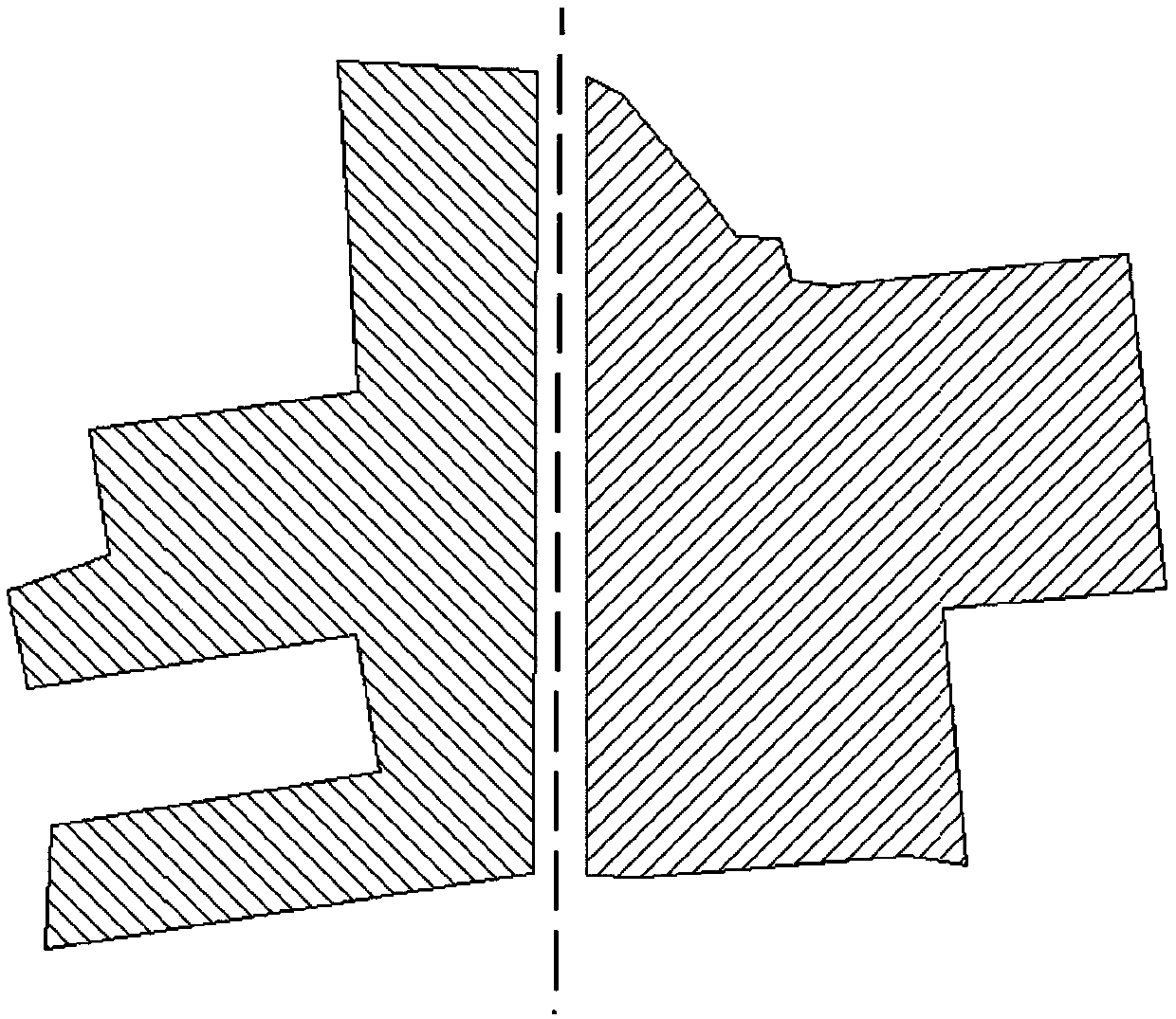
[0032] The invention can be used to realize fast and automatic border joining of massive complex planar element data. The raw data it processes are figure 1 As shown, the edge object to be connected is figure 1 The two area objects represented by the shadows on both sides. Its implementation steps are as follows.

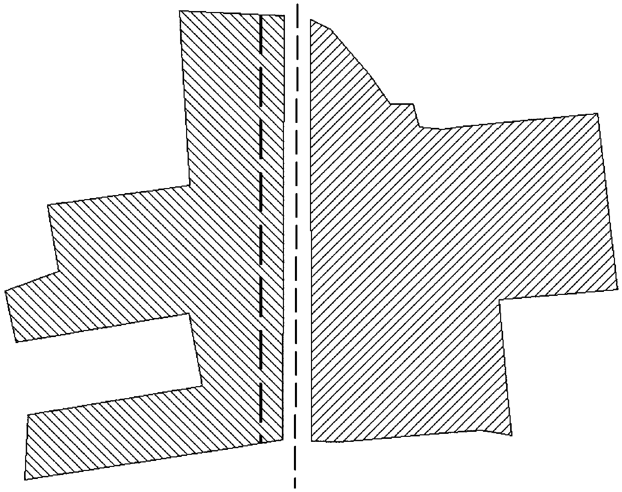
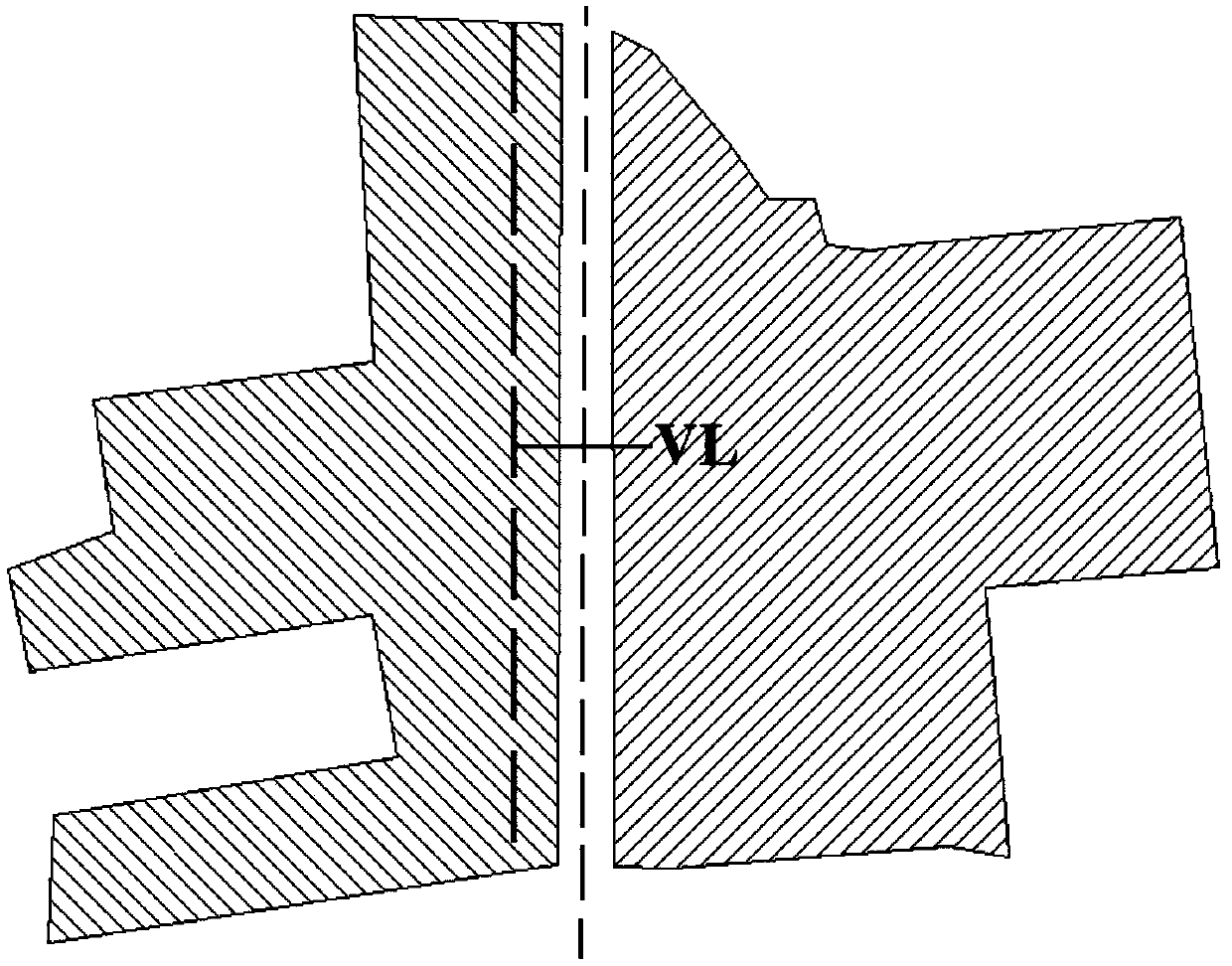
[0033] S1. Perform buffer processing on the linear map grid data according to the border tolerance value (the preset border tolerance is q) to form a buffer zone, and spatially intersect the area vector data to be bordered with the buffer zone (Intersect) relationship judgment, select the area vector data that intersects with the buffer zone to create ...


PUM


Abstract

The invention discloses a complex planar element automatic edge connection method based on a picture grid indentation technology. For the deviation of an operator in the operation process, an edge element to be spliced cannot be identified by a traditional edge splicing method. According to the method, automatic identification, automatic correction and edge splicing of the to-be-spliced edge elements are realized on the basis that intersection lines are extracted from the to-be-spliced edge element layers according to a spatial intersection relation after the planar image sheet grid data is subjected to inward shrinkage processing and converted into a line shape. According to the method, on the basis of making a vertical line at the center of an intersection line, spatial intersection relation selection is carried out on the intersection line and a to-be-spliced edge element layer to directly extract all to-be-spliced edge elements. Therefore, under the condition that deviation existsbetween the vector elements in the topographic map and the topographic map sheet grids, the elements needing edge connection can be obtained through the vertical lines of the intersection lines to besubjected to merging processing. Therefore, the deviation can be automatically corrected, and the edge connecting efficiency is higher and more accurate.

Description

technical field [0001] The invention relates to the field of geographic information data processing, in particular to an automatic edge joining method for complex planar elements based on the grid shrinkage technology of map frames. Background technique [0002] Digital Line Graphic (DLG for short) is the most important vector data product in the geographic information industry. Existing DLG products are produced by framing according to the national basic scale. When building a database and applying them in practice, it is necessary to process the DLG data frame by frame and element by element to seamlessly integrate the data. [0003] Although the existing geographic information system software has the function of map frame bordering, most of them have limitations: 1. Only two data frames are allowed to be bordered at the same time during the whole bordering process, resulting in low efficiency; 2. Many automatic bordering The edge algorithm only solves the geometric posit...

Claims


Application Information

Patent Timeline
Patent Type & Authority Applications(China)
IPC IPC(8): G06T3/40G06T7/32
CPCG06T3/4038G06T7/32
Inventor 金琳陶旸聂时贵石善球李翔刘玫
Owner 江苏省基础地理信息中心
Why Eureka
Try Eureka