Flue gas treatment system

A flue gas treatment system and flue gas technology are applied in the field of flue gas emission, which can solve the problem of high cost and achieve the effect of reducing project cost and saving industrial land.

Pending Publication Date: 2019-04-23
CHINA SHENHUA ENERGY CO LTD +3
View PDF0 Cites 4 Cited by
  • Summary
  • Abstract
  • Description
  • Claims
  • Application Information

AI Technical Summary

Problems solved by technology

[0003] The purpose of the present invention is to overcome the problem of high cost caused by the flue gas of power plants in the prior art, which often adopts the flue gas treatment device in the arrangement of "separation of smoke towers (indirect air cooling towers, desulfurization towe

Method used


Image

  • Flue gas treatment system
  • Flue gas treatment system
  • Flue gas treatment system

Examples


Embodiment Construction

[0021] Specific embodiments of the present invention will be described in detail below in conjunction with the accompanying drawings. It should be understood that the specific embodiments described here are only used to illustrate and explain the present invention, and are not intended to limit the present invention.

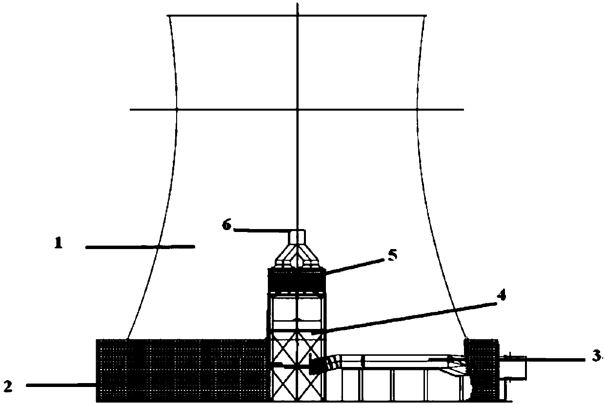
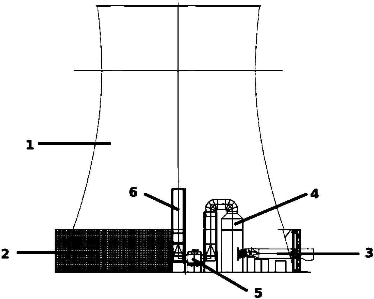
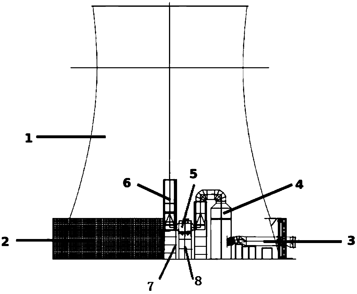
[0022] The first aspect of the present invention provides a flue gas treatment system, such as Figure 1-4 As shown, the flue gas treatment system includes a flue gas generating device, an indirect cooling tower 1, a flue gas purification unit and a chimney 6 arranged in the indirect cooling tower 1, and the bottom of the indirect cooling tower 1 includes an air intake structure and a radiator, the radiator is arranged at the air intake structure to heat the air at the air intake structure to obtain hot air, the flue gas generating device is arranged outside the indirect cooling tower 1 and is connected with the flue gas The inlet of the purification unit is co...


PUM


Abstract

The invention relates to the technical field of flue gas emission of a power plant, in particular to a flue gas treatment system. The flue gas treatment system comprises a flue gas generating device,an indirect cooling tower (1), and a flue gas purifying unit and a chimney (6) disposed in the indirect cooling tower. The bottom of the indirect cooling tower comprises an intake structure and a radiator for heating the air at the intake structure to obtain hot air disposed at the intake structure, and the flue gas generating device is disposed outside the indirect cooling tower and is communicated with the flue gas purifying unit, so that the flue gas in the flue gas generating device enters the flue gas purifying unit for purification treatment and a clean flue is obtained, the chimney is communicated with the flue gas purification unit and extends upward along the center line of the indirect cooling tower at least to the throat of the indirect cooling tower, so that the clean flue gasis discharged into the indirect cooling tower via the chimney and discharged under the carriage of the hot air. As the chimney and the flue gas purification unit are arranged in the indirect cooling tower, the flue gas treatment system saves the industrial land and achieves safety discharge of the flue gas.

Description

technical field [0001] The invention relates to the technical field of flue gas discharge in power plants, in particular to a flue gas treatment system. Background technique [0002] At present, indirect air-cooled coal-fired generating units in power plants are accompanied by a large amount of flue gas during operation, and corresponding flue gas treatment systems must be installed to pre-purify and discharge the large amount of flue gas, so that the flue gas discharged into the atmosphere The air meets the national emission standards, thereby reducing environmental pollution. At present, the flue gas of the power plant is routinely purified and discharged by the flue gas treatment system with the arrangement of "separation of smoke towers (indirect air cooling tower, desulfurization tower and chimney are arranged separately)". Specifically, the flue gas of the power plant first passes through the indirect air cooling tower, desulfurization tower The tower is purified, and...

Claims


Application Information

Patent Timeline
IPC IPC(8): B01D47/00B01D53/18F23J15/00F23J15/02F23J15/06F23J15/08
CPCB01D47/00B01D53/18F23J15/006F23J15/02F23J15/06F23J15/08F23J2215/20
Inventor 王树民宋畅田敬元李飞陈寅彪王福宁毛承慧刘新民张军峰张兴军郝卫王振国张京锁郝福龙韩晶李双江肖中图潘瑞华那尔苏杨金芳方永平阎占良崔智勇
Owner CHINA SHENHUA ENERGY CO LTD
Why Eureka
Try Eureka