Automatic loading and unloading device of laser cutter

A technology of automatic loading and unloading, laser cutting machine, used in laser welding equipment, welding equipment, metal processing equipment and other directions, can solve the problems of lower plate follow, safety accidents, damage to equipment, etc., to reduce the dependence of labor costs, reduce labor Strength, the effect of ensuring safety

Pending Publication Date: 2019-04-23
SUZHOU QUICK LASER TECH
View PDF0 Cites 2 Cited by
  • Summary
  • Abstract
  • Description
  • Claims
  • Application Information

AI Technical Summary

Problems solved by technology

Since most of the incoming materials of the boards are stacked, when the boards are automatically grabbed, it is easy to follow the phenomenon of the lower boards. As a result, when the uppermo

Method used


Image

  • Automatic loading and unloading device of laser cutter
  • Automatic loading and unloading device of laser cutter
  • Automatic loading and unloading device of laser cutter

Examples


Embodiment

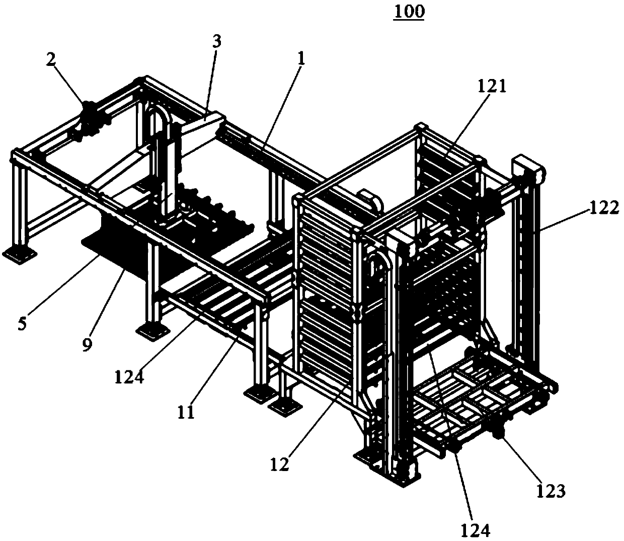
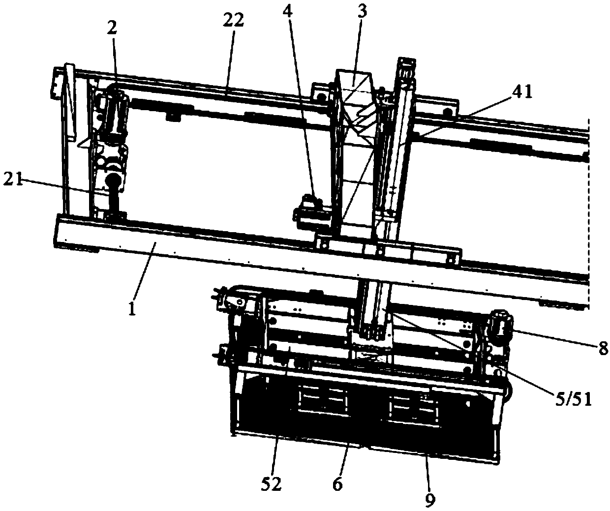
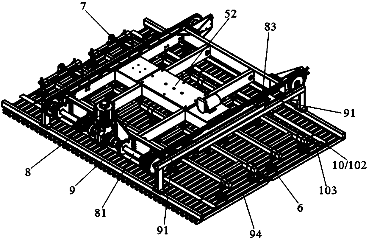
[0044] Please refer to Figure 1-Figure 15 , the present embodiment is an automatic loading and unloading device 100 for a laser cutting machine, which includes a transfer gantry steel frame 1, a horizontal transfer driver 2 fixed on the transfer gantry steel frame 1, and a horizontal transfer driver 2 driven The first support frame 3, the lifting driver 4 fixed on the first support frame 3, the second support frame 5 driven by the lifting driver 4 to move up and down, a number of suction nozzles 6 fixed below the second support frame 5, The disengagement mechanism 7 that is arranged at the outermost end of all the suction nozzles 6 and is used to disengage the uppermost plate and the lower plate, the claw driver 8 fixed on the second support frame 5, is driven by the claw driver 8 to move closer or closer A pair of claws 9 that are movable and located under all suction nozzles 6 .

[0045] The horizontal transfer driving part 2 is a servo motor, which is arranged at one end ...


PUM


Abstract

The invention discloses an automatic loading and unloading device of a laser cutter. The automatic loading and loading device comprises a transfer portal steel frame, a horizontal transfer drive partwhich is fixedly arranged on the transfer portal steel frame, a first supporting frame which is driven by the horizontal transfer drive part, a lifting drive part which is fixedly arranged on the first supporting frame, a second supporting frame which is driven by the lifting drive part to move up and down, a plurality of suction nozzles which are fixedly arranged below the second supporting frame, separating mechanisms which are arranged at the outermost ends of the suction nozzles for separating boards on the uppermost layer from boards at the lower layer, an insertion claw drive part whichis fixedly arranged on the second supporting frame, and a pair of insertion claws which are driven by the insertion claw drive part to oppositely get close to each other or perform opening motion andare positioned bellow all suction nozzles, wherein the second supporting frame comprises a vertical supporting plate and a horizontal supporting frame. The automatic loading and unloading device guarantees lifting stability and synchronism of a workbench, provides basis or horizontally transferring the workbench more smoothly, and improves field producing and working efficiency.

Description

【Technical field】 [0001] The invention belongs to the technical field of laser processing, in particular to an automatic loading and unloading device of a laser cutting machine. 【Background technique】 [0002] Due to its high flexibility and high precision, laser cutting occupies an increasingly important position in sheet metal processing, and it has a tendency to replace traditional sheet metal processing methods. With the development in recent years, the laser cutting machine has gradually changed from the original single-platform equipment to the current mainstream dual-platform or even multi-platform equipment. In the process of work, I found that although the dual platform can speed up the operating efficiency of the machine, it is still not friendly enough for the operator to load and unload, and there is a lot of workload. With the rise of labor costs, higher requirements are placed on the degree of automation of machining. The automatic loading and unloading effic...

Claims


Application Information

Patent Timeline
IPC IPC(8): B23K26/38B23K26/70
CPCB23K26/38B23K26/702
Inventor 李亚彬
Owner SUZHOU QUICK LASER TECH
Why Eureka
Try Eureka