
Magnetic press mounting positioning tool and using method thereof

A technology of positioning tooling and magnetic force, applied in positioning devices, manufacturing tools, metal processing equipment, etc., can solve the problems of high technical level requirements of operators, difficult clamping, low qualification rate, etc., and improve the flatness defect rate. , The effect of reducing the difficulty of clamping and uniform distribution of suction force

Active Publication Date: 2019-04-23
杭州联德精密机械股份有限公司
View PDF8 Cites 0 Cited by
  • Summary
  • Abstract
  • Description
  • Claims
  • Application Information

AI Technical Summary

Problems solved by technology

[0003] The invention overcomes the deficiencies of thinner workpieces being easily deformed when vertical clamping is used, difficult clamping, high technical level requirements for operators, and low qualified rate, and provides a magnetic press-fit positioning tool and its use method. It can realize horizontal clamping processing of thinner workpieces, and the clamping process is not easy to deform, greatly reducing the difficulty of clamping, simple and convenient operation, and greatly improving production efficiency and qualification rate

Method used


Image

  • Magnetic press mounting positioning tool and using method thereof
  • Magnetic press mounting positioning tool and using method thereof
  • Magnetic press mounting positioning tool and using method thereof

Examples


Embodiment 1

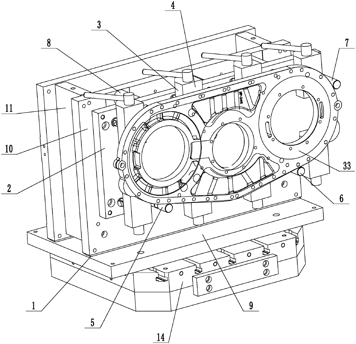
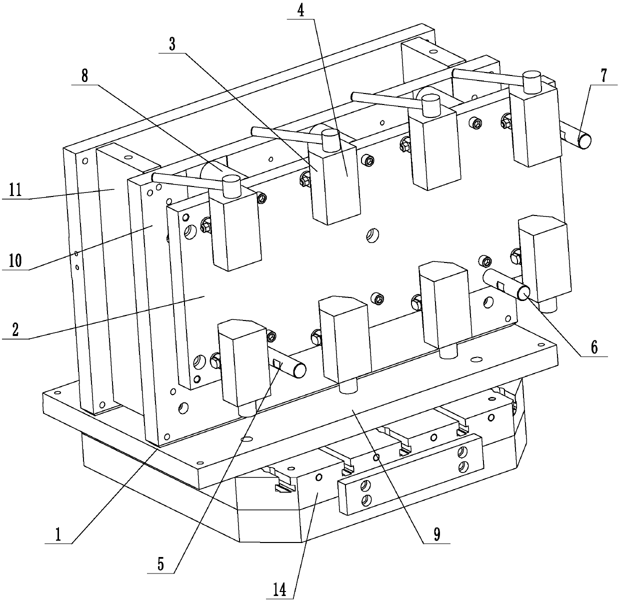
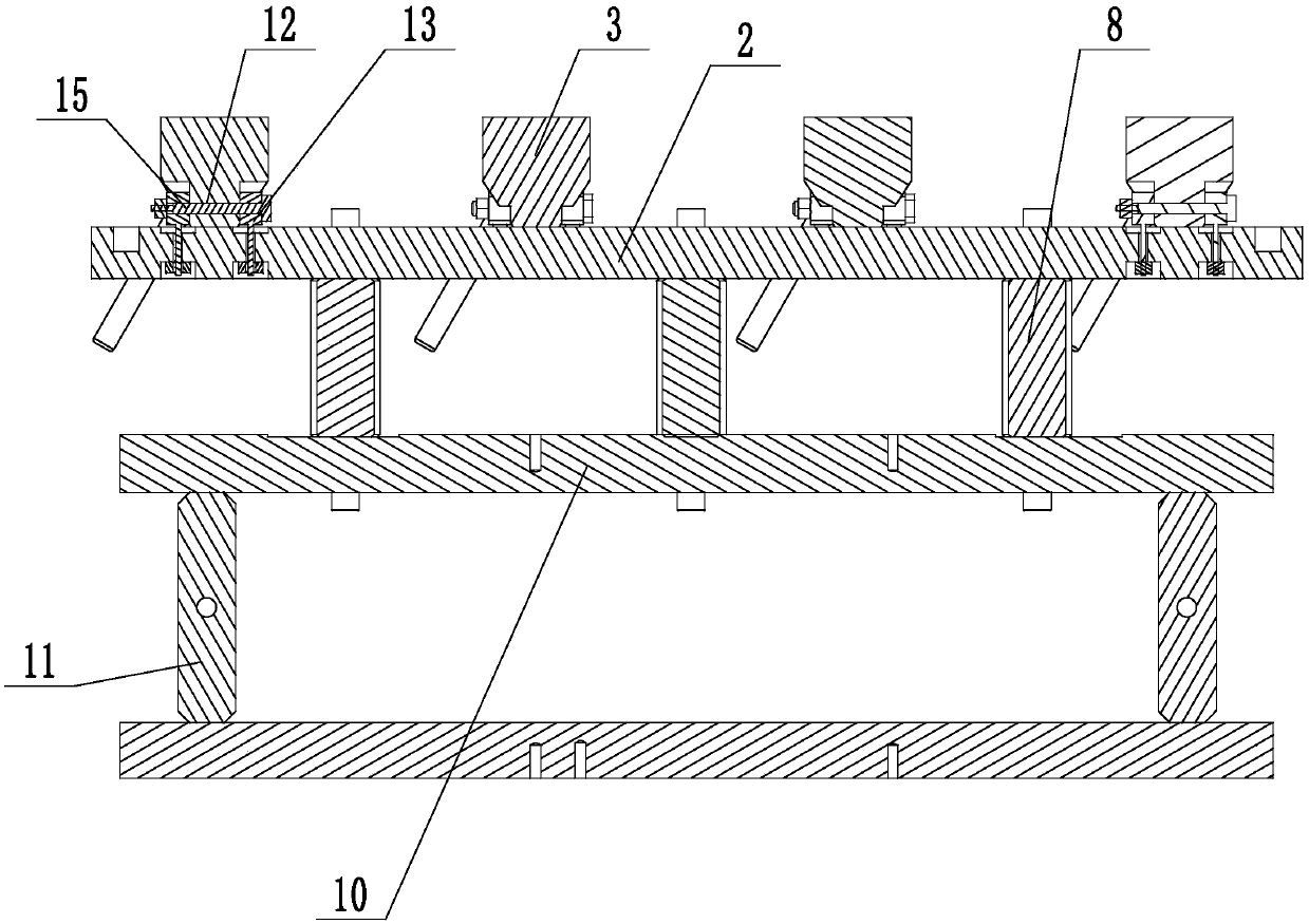
[0023] Embodiment 1: A magnetic press-fit positioning tool (see attached figure 1 To attach image 3 ), including a base 1, a bottom plate 2 vertically connected to the base, a number of electromagnetic blocks 3 are fastened on the bottom plate, and the surface of the electromagnetic block away from the bottom plate is a suction support surface 4 with a planar structure, and the bottom left positioning is installed on the bottom plate Column 5, lower right positioning column 6, upper right positioning column 7, the lower left positioning column is placed on the left side of the lower edge of the bottom plate, the lower right positioning column is placed on the right side of the lower edge of the bottom plate, and the upper right positioning column is placed on the upper right edge of the bottom plate , along the normal direction of the base plate, the lower left positioning column, the lower right positioning column, and the upper right positioning column are all higher than t...

Embodiment 2

[0025] Embodiment 2: A magnetic press-fit positioning tool (see attached Figure 4 ), its structure is similar to that of Embodiment 1, the main difference is that in this embodiment, a negative pressure groove 16 is provided on the suction support surface of the electromagnetic block, a sealing ring 17 is installed on the opening edge of the negative pressure groove, and a negative pressure groove is connected to the electromagnetic block. The negative pressure pipe 18 that pressure groove communicates with, the suction pump is installed on the base plate, and the negative pressure pipe is all connected with the suction pump. Other structures are the same as in Embodiment 1. When the electromagnetic block is attracted to the workpiece, the suction pump is started to pump air into the negative pressure tank, so that a negative pressure is formed in the negative pressure tank, thereby increasing the adsorption force of the suction support on the surface of the workpiece.

[00...

Embodiment 3

[0027] Embodiment 3: A magnetic press-fit positioning tool (see attached Figure 5 , attached Figure 6 ), its structure is similar to that of Embodiment 1, the main difference is that in this embodiment, a negative pressure groove 16 is provided on the suction support surface of the electromagnetic block, a sealing ring 17 is installed on the opening edge of the negative pressure groove, and a negative pressure groove is connected to the electromagnetic block. The negative pressure pipe 18 that pressure groove communicates with, the suction pump is installed on the base plate, and the negative pressure pipe is all connected with the suction pump. Other structures are the same as in Embodiment 1. When the electromagnetic block is attracted to the workpiece, the suction pump is started to pump air into the negative pressure tank, so that a negative pressure is formed in the negative pressure tank, thereby increasing the adsorption force of the suction support on the surface of...


PUM


Abstract

The invention discloses a magnetic press mounting positioning tool and a using method thereof and aims at solving the deficiencies that a thinner workpiece is liable to deform, large in the clamping difficulty, high in requirement for the technical level of operators and low in qualified rate when vertical clamping processing is adopted. The magnetic press mounting positioning tool comprises a base and a bottom plate vertically connected to the base; the bottom plate is provided with a plurality of electromagnetic blocks in a fastening manner; the surface, away from the bottom plate, of each electromagnetic block is a suction supporting surface of a plane structure; the bottom plate is provided with a left lower positioning column, a right lower positioning column and a right upper positioning column; the left lower positioning column is arranged at the left position of the lower edge of the bottom plate; the right lower positioning column is arranged at the right position of the loweredge of the bottom plate; the right upper positioning column is arranged at the upper position of the right edge of the bottom plate; and the left lower positioning column, the right lower positioning column and the right upper positioning column are all higher than the suction supporting surfaces on the electromagnetic blocks in a normal direction of the bottom plate. The tool is convenient in workpiece clamping operation and reliable in clamping and positioning, improves the production efficiency and increases the qualified rate.

Description

technical field [0001] The present invention relates to a positioning tool, more specifically, it relates to a magnetic pressing positioning tool and its usage method. Background technique [0002] At present, the manufacturing process plan of each product of the company is formulated according to the processing characteristics of various products and the characteristics of various CNC machine tools of the company. When the workpiece is clamped in vertical machining, since the workpiece is thin, in order to prevent deformation of the workpiece, it is necessary to position the workpiece with several equal-height supports first, then tighten several side supports in a certain order according to the specified torque force, and then press Sequentially tighten several height-adjustable auxiliary supports slightly against the bottom surface of the workpiece, and when finishing the large surface, several side tops need to be loosened to prevent clamping deformation, which greatly i...

Claims


Application Information

Patent Timeline
Patent Type & Authority Applications(China)
IPC IPC(8): B23Q3/154B23Q3/08B23Q3/18
CPCB23Q3/088B23Q3/1543B23Q3/18
Inventor 孙袁苟富明朱燚威王顺
Owner 杭州联德精密机械股份有限公司
Learn More