A cutting fluid circulation system in a stainless steel processing workshop

A processing workshop and circulation system technology, applied in the direction of metal processing equipment, metal processing machinery parts, manufacturing tools, etc., can solve the problems of large footprint, scattered equipment, difficult separation and dumping, etc., to achieve high practical value and promotion prospects , scientific distribution of equipment, and the effect of improving the recycling system

Active Publication Date: 2020-06-26
浙江元畅不锈钢科技有限公司
View PDF14 Cites 2 Cited by
  • Summary
  • Abstract
  • Description
  • Claims
  • Application Information

AI Technical Summary

Problems solved by technology

[0003] In stainless steel processing workshops, oily cutting fluids are generally used. In the prior art, in order to save costs, save energy and reduce emissions, a cutting fluid circulation recovery system is usually installed in the workshop. The system uses a pump unit to make the cutting fluid form a loop, and filter treatment in this loop, so that the cutting fluid and metal residues are separated, so that they can be reused, but the following defects exist in the existing recovery system: 1. The equipment in the circulation system is relatively scattered and occupies a large area; 2. Cutting fluid is easily stratified by residues during filtration and separation, and the oily liquid in the upper layer will be taken away by metal residues, or directly stay on the separation equipment, resulting in a decrease in concentration; 3. During the processing stage of cutting fluid in the circulation system, moisture There will be a certain amount of evaporation, resulting in a change in the pH value; 4. In the filtration process, the separated metal residues have a certain amount of oily liquid, so they stick to each other and are not easy to separate and dump

Method used


Image

  • A cutting fluid circulation system in a stainless steel processing workshop
  • A cutting fluid circulation system in a stainless steel processing workshop
  • A cutting fluid circulation system in a stainless steel processing workshop

Examples


Embodiment

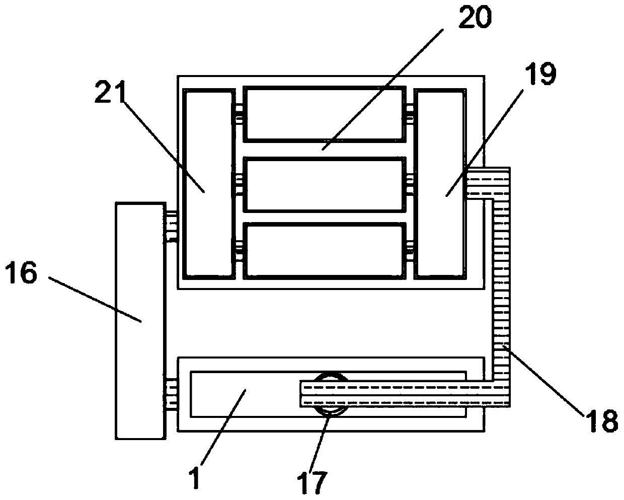
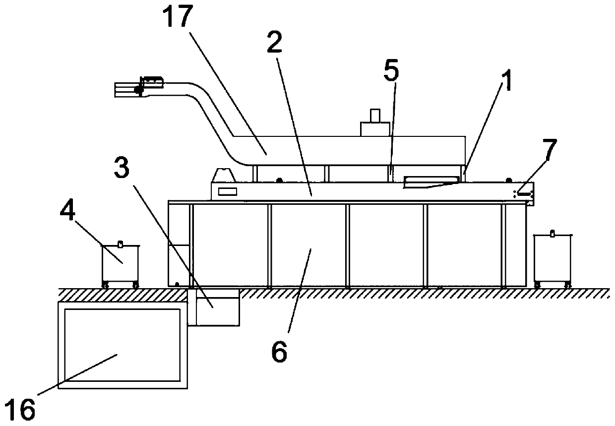
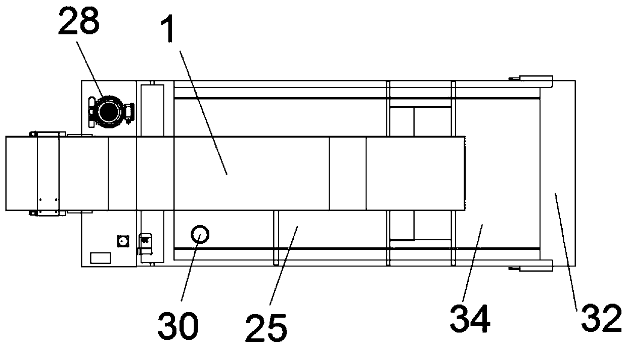
[0028] Embodiment: a cutting fluid circulation system in a stainless steel processing workshop, as attached Figure 1-10 As shown, a cutting fluid circulation system in a stainless steel processing workshop is characterized in that it includes a processing equipment group 20, a circulation tank 16, and a filtration system 1. A cutting fluid recovery pipe is arranged in the processing equipment group 20, and the processing equipment group 20 is connected with the filtering system 1. The systems 1 are connected through the first comprehensive tank 19, and the processing equipment group 20 and the circulation tank 16 are connected through the second comprehensive tank 21. Both the first comprehensive tank 19 and the second comprehensive tank 21 are provided with pressurized pump groups. The first comprehensive tank 19 communicates with a primary filter channel 17 through the delivery pipeline 18, and one end of the primary filter channel 17 is installed above the filter system 1 t...


PUM


Abstract

The invention discloses a cutting fluid circulation system in a stainless steel processing workshop, comprising a processing equipment group, a circulation tank and a filtering system. The processing equipment group and the filtering system are communicated through a first integrated tank, and the first integrated tank passes through The conveying pipeline is communicated with a primary filtering channel, a secondary filtering channel is arranged below the primary filtering channel, a mixing chamber is provided below the secondary filtering channel, and a vortex stirrer is arranged in the mixing chamber, and the mixing A solvent box and a preparation box are fixedly installed on the outer side wall of the cavity, an injector is installed at the connection between the solvent box and the preparation box and the preparation cavity, and both ends of the filter system are provided with residue recovery bins. In the present invention, the cutting fluid in the workshop is formed into a circulating circuit through the pressurized pump group, and the used cutting fluid is filtered, separated, transported and allocated in the circuit. After the processed cutting fluid meets the conditions, the Transfer to the processing end for matching processing.

Description

technical field [0001] The invention relates to stainless steel processing, in particular to a cutting fluid circulation system in a stainless steel processing workshop. Background technique [0002] Cutting fluid is an industrial liquid used in metal cutting and grinding to cool and lubricate cutting tools and workpieces. Cooling performance, lubricating performance, anti-rust performance, degreasing and cleaning function, anti-corrosion function, easy to dilute. [0003] In stainless steel processing workshops, oily cutting fluids are generally used. In the prior art, in order to save costs, save energy and reduce emissions, a cutting fluid circulation recovery system is usually installed in the workshop. The system uses a pump unit to make the cutting fluid form a loop, and filter treatment in this loop, so that the cutting fluid and metal residues are separated, so that they can be reused, but the following defects exist in the existing recovery system: 1. The equipment...

Claims


Application Information

Patent Timeline
Patent Type & Authority Patents(China)
IPC IPC(8): B23Q11/10B01D33/048B01D33/00B01D33/80
CPCB01D33/048B01D33/333B01D33/804B23Q11/1069
Inventor 张健倪晓东梁成超
Owner 浙江元畅不锈钢科技有限公司
Why Eureka
Try Eureka