Automation tube shoulder injection equipment

A technology of automation equipment and tubular objects, which is applied in the field of hose manufacturing, can solve the problems of low efficiency and difficult labor, and achieve the effects of high efficiency, good accuracy and stable running trajectory.

Pending Publication Date: 2019-04-23
常州市泓帆自动化设备有限公司
View PDF1 Cites 5 Cited by
  • Summary
  • Abstract
  • Description
  • Claims
  • Application Information

AI Technical Summary

Problems solved by technology

[0004] The purpose of the present invention is to overcome the defects existing in the prior art, and provide a method that can solve the problems of production safety, misplaced materials, low efficiency, and difficult labor in the existing manual operation, and has the advantages of reasonable structure, good precision, low cost, and high efficiency. Advantages of tubular shoulder injection automation equipment

Method used


Image

  • Automation tube shoulder injection equipment
  • Automation tube shoulder injection equipment
  • Automation tube shoulder injection equipment

Examples


Embodiment 1

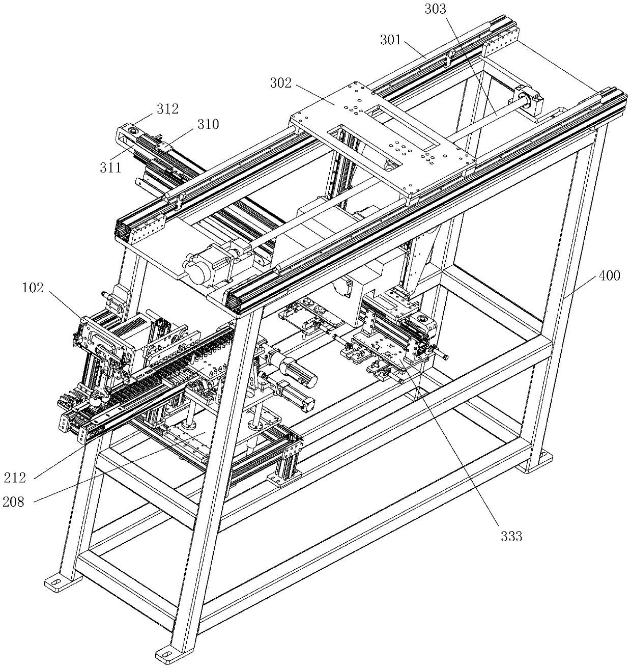
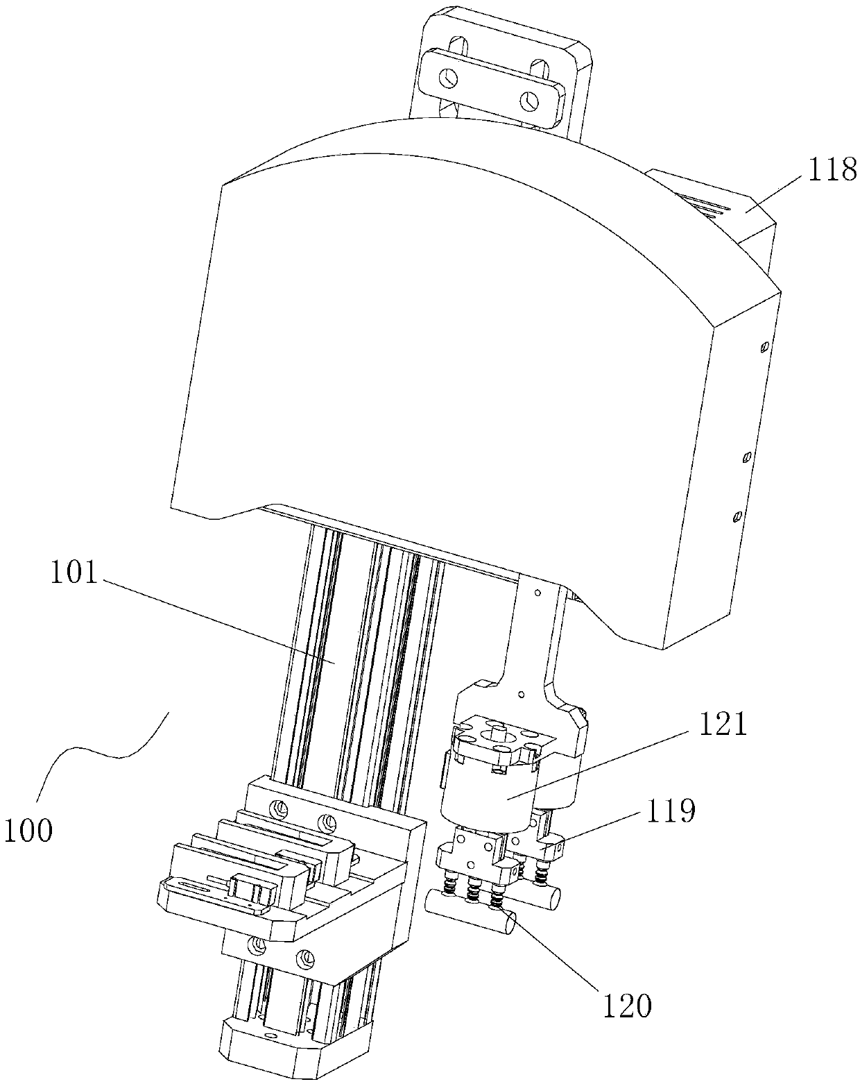
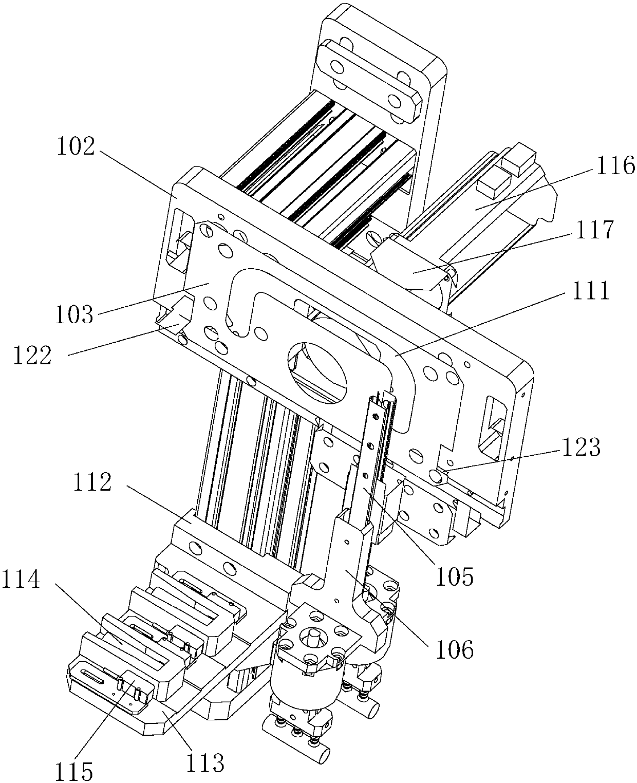
[0070] See Figure 1 to Figure 13, the present invention relates to an automatic equipment for injecting shoulders of tubular objects, which has a frame 400, a feeding mechanism and an injection molding machine; the frame 400 is arranged on one side of the injection molding machine; the feeding mechanism is arranged at the input end of the feeding and discharging device; The other side of the injection molding machine is equipped with a waste clamping manipulator; the frame 400 is equipped with a loading and grabbing device 100, a feeding and discharging device 200 and a clamping translation transfer transfer device 300; the loading and grabbing device 100 is installed on One side of the feeding mechanism, and is installed at the input end of the feeding and discharging device 200 at the same time; the feeding and grabbing device 100 has a feeding rack 101; the upper end of the feeding rack 101 is fixed with a grabbing device, and the middle part corresponds to the grabbing dev...

Embodiment 2

[0108] Wherein, two to three groups of conveying frocks 223 are installed on the synchronous belt 202, the number of one group of conveying frocks 223 is twice the number of comb teeth of the push plate 207, the synchronous belt 202 reciprocates, and the intermediate transition frock 212 can be The distance between the turning mechanism mounting plate 208 and the synchronous belt 202 is adjustable for disassembly and replacement.

[0109] According to different needs, different types of conveying tooling 223 can be manually adjusted to a good position. When working, the materials are discharged into the conveying tooling 223, and the materials on the same group of conveying tooling 223 are pushed to the intermediate transitional tooling 212 twice. Complete the insertion of a version of the intermediate transition tooling 212, at this time, the timing belt 202 resets, returns to the initially adjusted position, and continues to discharge materials, so reciprocating.

[0110] Th...

Embodiment 3

[0112] See Figure 14 and Figure 15 , the feeding mechanism of the present invention includes a first feed bin 501, a second feed bin 502, and a feeding conveying mechanism installed on the feed rack 500; There is a first material-loading lifting mechanism; a second material-loading lifting mechanism is provided between the second material bin 502 and the material-loading conveying mechanism.

[0113] A sieve plate installation frame 503 is installed on the material feeding and conveying mechanism; a sieve material slide plate 504 is provided on the sieve material side of the sieve material plate installation frame 503 .

[0114] The first feeding lifting mechanism includes a first feeding lifting drive mechanism, a driving shaft, a driven shaft, a first feeding conveyor belt 505 and a brush plate 506; The bearing seat 507 drives the driving shaft to rotate; the driving shaft and the driven shaft are installed on the upper end of the material lifting bracket 508 inclined to...


PUM


Abstract

The invention relates to automation tube shoulder injection equipment. The equipment comprises a frame, a feeding mechanism and an injection molding machine, wherein the frame is arranged on one sideof the injection molding machine; the feeding mechanism is arranged at an input end of a feeding and discharging device; the frame is provided with a feeding grasping device, the feeding and discharging device and a clamping translation transfer carrying device; the feeding grasping device is installed on one side of the feeding mechanism and also installed at the input end of the feeding and discharging device; and the clamping translation transfer carrying device is installed above an intermediate transition tool of the feeding and discharging device. The automation tube shoulder injection equipment is suitable for the production of toothpaste hoses, shoe oil hoses, glue hoses, cosmetic hoses and the like. Therefore, the automation tube shoulder injection equipment has the advantages such as reasonable structure, good precision, low cost and high efficiency.

Description

technical field [0001] The invention relates to the technical field of hose manufacturing, in particular to an automatic equipment for injecting shoulders on tubular objects. Background technique [0002] The traditional manual stamping production line has problems such as low production efficiency, many human factors, unstable product quality, increasing production costs and labor costs year by year, which makes the domestic shift from manual production lines to automated production equipment. The automatic tubular injection shoulder production equipment is mainly composed of injection molding machine, mold and tubular injection shoulder. At present, all are produced by manual operation: the manual handling of tubular materials is replaced by automation, thereby avoiding personal safety problems caused by monotonous, frequent and repetitive long-term operations. Using automation to solve the problem of tubular injection shoulders has many advantages, which can effectively ...

Claims


Application Information

Patent Timeline
Patent Type & Authority Applications(China)
IPC IPC(8): B29C45/17
CPCB29C45/17B29C2045/1784
Inventor 周志玉周大军张金海付代新
Owner 常州市泓帆自动化设备有限公司
Why Eureka
Try Eureka