
Forming and die releasing device for injection molding die gear and injection molding device thereof

A technology of injection mold and demoulding device, which is applied in the field of injection mold gear forming and demoulding device and its injection molding equipment, can solve the problems of high cost, large product interference, difficulty in applying core molding scheme, etc., and achieve the effect of guaranteed effect

Inactive Publication Date: 2019-04-23
SHENZHEN SKYWORTH PRECISION TECH
View PDF9 Cites 4 Cited by
  • Summary
  • Abstract
  • Description
  • Claims
  • Application Information

AI Technical Summary

Problems solved by technology

[0002] Injection molding is a processing method used in the mass production of some parts with complex shapes. When producing products with a helical gear shape, if you rely on the traditional core molding solution, because the side of the product is a helical helix angle, the vertical top The helix angle of the product is the pressure angle between the core and the product. A large part of the ejection force will be converted into the extrusion force and friction between the product and the core. The ejection system will be driven by the hydraulic system of the injection molding equipment. , the product is made of plastic and its size is small, so it will be directly destroyed, so the traditional core molding solution is difficult to apply
[0003] If relying on the slider forming scheme, set a slider on each side of the product to form a cavity for molding the product. However, because the product is a helical gear shape, it has a large oblique helix angle, and the wrap angle with the product is greater than 180. °, so there is a lot of interference with the product
For example, using multiple sliders can theoretically achieve the purpose of forming, but the cost is high and the efficiency is low, so it is not suitable for actual production

Method used


Image

  • Forming and die releasing device for injection molding die gear and injection molding device thereof
  • Forming and die releasing device for injection molding die gear and injection molding device thereof
  • Forming and die releasing device for injection molding die gear and injection molding device thereof

Examples


Embodiment Construction

[0025] The present invention will be described in further detail below in conjunction with the accompanying drawings.

[0026] This specific embodiment is only an explanation of the present invention, and it is not a limitation of the present invention. Those skilled in the art can make modifications to this embodiment without creative contribution as required after reading this specification, but as long as they are within the rights of the present invention All claims are protected by patent law.

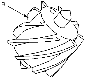
[0027] Such as figure 1 As shown, the helical teeth on the side of the product 9 to be processed have a relatively large helix angle, so it is very difficult to directly eject the product 9 from the mold. In this application, the demoulding is performed by rotating the core to ensure the effect of molding and demoulding .

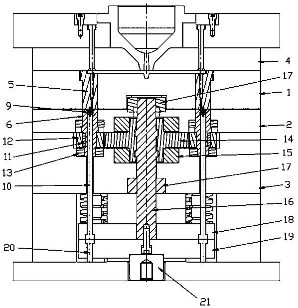
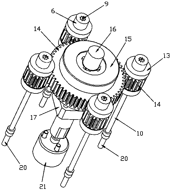
[0028] Such as figure 2 As shown, the present application provides an injection mold gear forming and demoulding device, including an injection molding ass...


PUM


Abstract

The invention discloses a forming and die releasing device for an injection molding die gear and an injection molding device thereof. The forming and die releasing device for the injection molding diegear comprises an injection molding assembly, a forming chamber assembly and a rotating push-out mechanism, wherein the forming chamber assembly comprises a mold cavity which is arranged on a fixed die plate and is connected to the injection molding assembly, and a mold core which fits the mold cavity and is arranged on a movable die plate; and the rotating push-out mechanism comprises a rotatingdriving assembly for driving the mold core to rotate, and a push-out driving assembly which is used for pushing out a product from the mold core while the mold core rotates. According to the formingand die releasing device for the injection molding die gear, the product is pushed out while the mold core rotates so as to realize die releasing, and thus a product with a large oblique tooth helicalangle on the side surface applies, and the product forming and die releasing effects can be ensured.

Description

technical field [0001] The invention relates to the field of injection molds, more specifically, it relates to an injection mold gear forming and demoulding device and injection molding equipment thereof. Background technique [0002] Injection molding is a processing method used in the mass production of some parts with complex shapes. When producing products with a helical gear shape, if you rely on the traditional core molding solution, because the side of the product is a helical helix angle, the vertical top The helix angle of the product is the pressure angle between the core and the product. A large part of the ejection force will be converted into the extrusion force and friction between the product and the core. The ejection system will be driven by the hydraulic system of the injection molding equipment. , the product is made of plastic and its size is small, so it will be directly destroyed, so the traditional core molding solution is difficult to apply. [0003]...

Claims


Application Information

Patent Timeline
Patent Type & Authority Applications(China)
IPC IPC(8): B29C45/40B29C45/66
CPCB29C45/40B29C45/4005B29C45/66
Inventor 袁建忠张松平龙章汉潘文军梅中政
Owner SHENZHEN SKYWORTH PRECISION TECH
Learn More