Jig structure

A side wall and arc angle technology, applied in the field of fixtures, can solve problems such as easy to wrinkle, difficult to shape, and unable to meet the design trend of four-sided curved glass

Active Publication Date: 2019-04-23
INTERFACE TECH CHENGDU CO LTD +2
View PDF13 Cites 3 Cited by
  • Summary
  • Abstract
  • Description
  • Claims
  • Application Information

AI Technical Summary

Problems solved by technology

However, such a design still cannot meet the design trend of four-sided curved glass. When the film

Method used


Image

  • Jig structure
  • Jig structure
  • Jig structure

Examples


Embodiment Construction

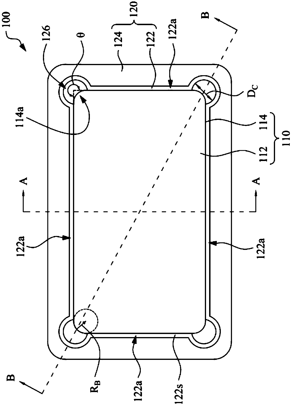
[0029] The jig structure 100 of this embodiment can be used for thermoforming a film, such as four-curved surface thermoforming.

[0030] For example, the film base material that can be used for thermoforming processing can be a material with low dielectric constant, high light transmission and other properties suitable for touch sensing films, such as polyethylene terephthalate (PET), Cycloolefin polymer (COP), and polymethyl methacrylate (PMMA), etc.

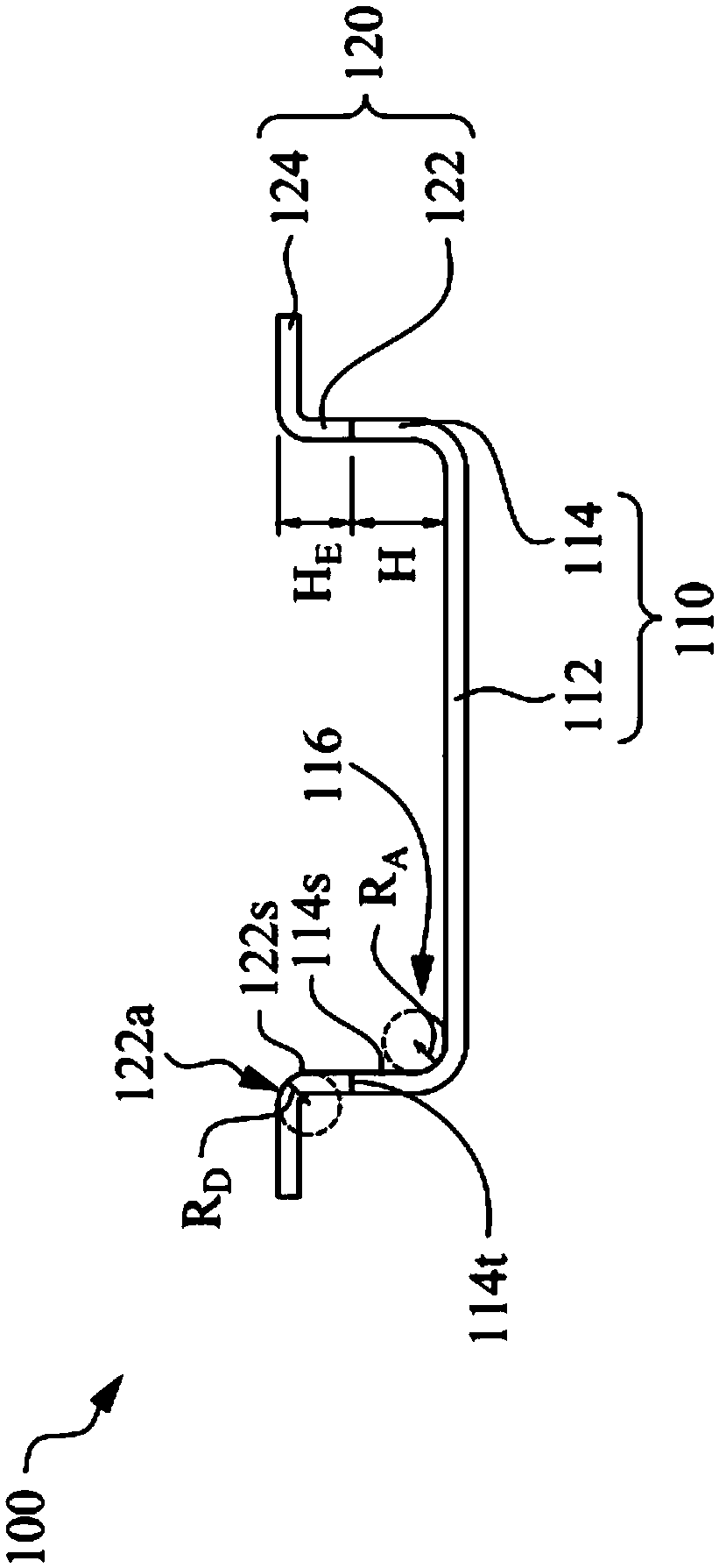
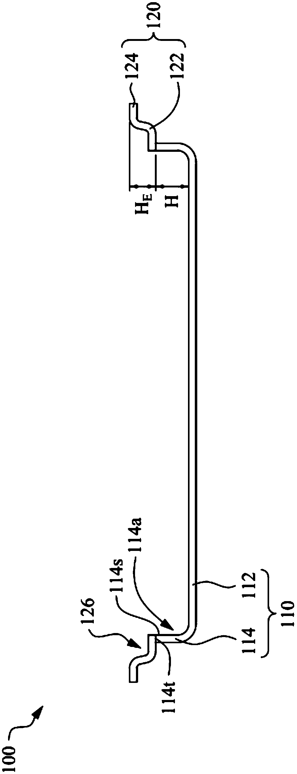
[0031] Such as figure 1 and figure 2 As shown, in some embodiments, the jig structure 100 mainly includes a main body 110 and a spacer 120 . The internal shape and size of the main body 110 match the shape of the film to be formed. The main body 110 mainly includes a bottom plate 112 and a first side wall 114 , wherein the bottom plate 112 may have a square or rectangular plate-like structure. The first side wall 114 is erected on the edge of the bottom plate 112 and surrounds the bottom plate 112 in a peripheral manner. ...


PUM

PropertyMeasurementUnit
Radiusaaaaaaaaaa
Heightaaaaaaaaaa

Abstract

The invention provides a jig structure. The jig structure comprises a main body and a spacer. The main body comprises a bottom plate and a first side wall. The first side wall is arranged on the edgeof the bottom plate in a surrounding mode, and four first corner guiding parts are arranged between the first side wall and the bottom plate. The first side wall is provided with four arc angles. Thespacer comprises a second side wall and an extension part. The second side wall is connected to the top surface of the first side wall, and the inner side surface of the second side wall is aligned with the inner side surface of the first side wall. The second side wall is provided with four second corner guiding parts located on the inner side surface of the second side wall, and four arc groovescorrespond to the adjacent arc angles respectively and are located on the outer sides of the corresponding arc angles respectively. The extension part extends from the top of the second side wall tothe outside of the second side wall. The arc grooves can provide the extension space of the thin film during thermal forming and stretching, and the strain amount of the thin film can be reduced, so that wrinkles or warping of the thin film during hot forming can be avoided.

Description

technical field [0001] The present invention relates to a jig, and in particular to a jig structure capable of four-sided curved thermoforming. Background technique [0002] In order for the film to be bonded to the four-curved glass, the film must be thermoformed. However, the design trend of today's four-sided curved glass is small curvature and large bending angle, and under this trend, the current thermoforming process is not easy to shape the four corners of the film. [0003] The design of the thermoforming jig for the film will be made according to the shape to be formed. At present, there is a proposed technology, which is to install gaskets on the top of the original jig to increase the height of the overall side wall of the jig structure, so as to increase the contact area of ​​the film with the corner of the jig structure during thermoforming. However, such a design still cannot meet the design trend of four-sided curved glass. When the film is thermoformed, it ...

Claims


Application Information

Patent Timeline
IPC IPC(8): B29C51/30B29L7/00
CPCB29C51/30B29L2007/00
Inventor 陈圣哲曹叶廷
Owner INTERFACE TECH CHENGDU CO LTD
Why Eureka
Try Eureka