
Collision energy absorbing box based on paper cutting pattern design

A technology of crash energy absorption and pattern design, which is applied in vehicle safety arrangements, bumpers, transportation and packaging, etc., can solve the problems that affect the actual demand of crash energy absorbing boxes, long production cycle of crash energy absorbing boxes, and excessive initial peak force load. Large and other problems, to achieve strong designability, reduce processing costs, and reduce peak load effects

Active Publication Date: 2019-04-23
DALIAN UNIV OF TECH
View PDF10 Cites 5 Cited by
  • Summary
  • Abstract
  • Description
  • Claims
  • Application Information

AI Technical Summary

Problems solved by technology

For example, in the patent titled "Automobile energy-absorbing box based on periodic honeycomb structure core" and the publication number is CN107856743A, the structure is formed by continuous expansion of honeycomb cells in three-dimensional space, with high energy absorption density and stable energy absorption. High resistance, but there is still the problem of excessive initial peak force load
In terms of reducing the initial peak force, it is an effective solution to change the thickness of the wall of the crash box, which is called "a car crash box with continuously variable thickness". The continuously variable-thickness steel plates that gradually thicken from the front end to the rear end form a crash absorber. Due to different stiffness distributions, they can collapse sequentially during a collision in a symmetrical telescopic manner. However, the disadvantage of this method is that the crash absorber The production cycle is long, the process is difficult, and the processing cost is high, which affects the actual demand for crash boxes

Method used


Image

  • Collision energy absorbing box based on paper cutting pattern design
  • Collision energy absorbing box based on paper cutting pattern design
  • Collision energy absorbing box based on paper cutting pattern design

Examples


Embodiment 1

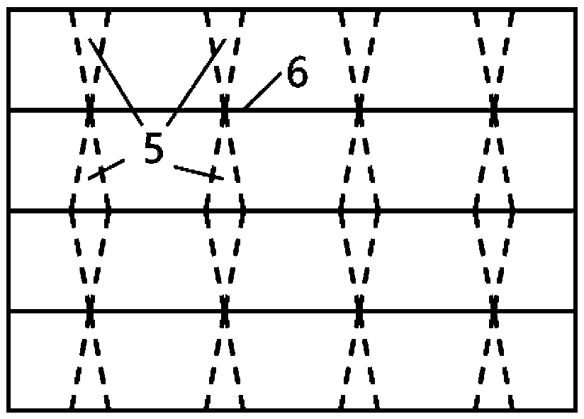
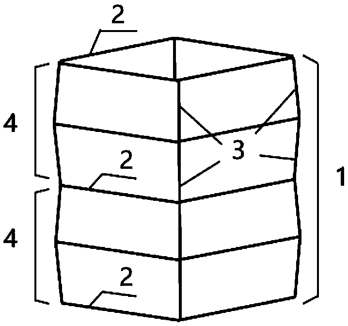
[0038] Embodiment 1: An embodiment of a collision crash box with a paper-cut pattern of a square cross-section as shown in FIG. 1(a) and FIG. 1(b).

[0039] The so-called paper-cut pattern collision energy-absorbing box with square cross-section means that the square cross-section 2 of the square-section paper-cut pattern collision energy-absorbing box is a square. Using the second processing technology, the crash box is assembled from two identical modules. Figure 1(a) is a schematic diagram of the planar expansion of the crash box with a paper-cut pattern of a square section, and Figure 1(b) is a square section The forming drawing of the collision energy-absorbing box with paper-cut pattern is used to specifically describe the shape design of the collision energy-absorbing box 1 with paper-cut pattern of square section. In the present invention, the crash box adopts a modular design concept, wherein the single module 4 of the crash box with a paper-cut pattern of a square sect...

Embodiment 2

[0041] Embodiment 2: Fig. 3(a) and Fig. 3(b) are an embodiment of a collision crash box with variable cross-section and a square-section paper-cut pattern.

[0042] Variable cross-section means that the cross-sections at the same position of different units along the axial direction are changed. Compared with the square-section paper-cut pattern collision crash box described in Embodiment 1, this kind of variable-section crash box only needs Just change the paper-cut pattern in Figure 1(a). The adjusted kirigami pattern is shown in Fig. 3(a). The variable-section square-section kirigami pattern collides with the energy-absorbing box 7 and the variable-section square-section kirigami pattern collides with the single module 8 of the energy-absorbing box, as shown in the figure. In addition to the square section, Crash boxes with other cross-sectional kirigami patterns can also be obtained by modifying the number and shape of the kirigami patterns, and examples are not given here...

Embodiment 3

[0043] Embodiment 3: Fig. 4(a) and Fig. 4(b) are an embodiment of a collision crash box with a square-section paper-cut pattern with an equal-section end frame.

[0044] The so-called square-section paper-cut pattern collision energy-absorbing box with an equal-section end frame means that the section of the energy-absorbing box is square. And from the appearance, it is spliced ​​by ordinary square section tubes and paper-cut pattern tubes. However, it can be seen from Figure 4(a) that the design of kirigami patterns is not limited to a single geometric figure, and can be designed by introducing combined patterns. Similarly, the lengths of the individual modules 10 of the crash box with square-section paper-cut patterns with equal-section end frames in the axial direction can also be different, and the single modules 10 of the crash-absorbing box with square-section paper-cut patterns with equal-section end frames The boundary 3 may also be different after the paper-cut patte...


PUM


Abstract

The invention belongs to the technical field of the anti-collision structure manufacturing of traffic vehicles such as automobiles and trains, and relates to a collision energy absorbing box based onpaper cutting pattern design. In a manufacturing process of a thin-wall pipe fitting, according to different design requirements, excess materials are removed; paper cutting patterns are introduced; and finally a specific deformation mode is guided. Compared with a common collision energy absorbing box, a thin-wall pipe in the collision energy absorbing box involved in the invention can be axiallydivided into a plurality of similar modules; and the processing and manufacturing of the paper cutting patterns are performed in corner areas of each module, so that fold lines in different angles are formed according to the different paper cutting patterns. According to the invention, through introducing the paper cutting patterns and removing the excess materials, the functions of the collisionenergy absorbing box is realized and meanwhile, the requirements of low peak force and high average force are met; the paper cutting patterns involved in the invention are convenient for cutting andprocessing; a whole structure can be formed by cutting a piece of a thin flat plate; a processing technology is relatively simple; the processing cost is greatly reduced; and the accuracy of processing also can be improved.

Description

technical field [0001] The invention belongs to the technical field of manufacturing anti-collision structures for vehicles such as automobiles and trains, and relates to a collision energy-absorbing box designed based on paper-cut patterns, in particular to a collision energy-absorbing box device capable of absorbing kinetic energy during collisions of various vehicles , is a design for personal and cargo safety during accidental collisions. Background technique [0002] With the continuous development of science and technology, the running speed of various ground vehicles is constantly accelerating, followed by the gradual reduction of life and property protection after collisions and accidents. At present, the effective way to prevent the serious consequences of collision accidents is to install specially designed collision energy-absorbing boxes in the sections where various vehicles are prone to contact. Common crash boxes are thin-walled metal pipe fittings and variou...

Claims


Application Information

Patent Timeline
IPC IPC(8): B60R19/02
CPCB60R19/023B60R2019/026
Inventor 周才华王博李桐宋志博明世朝郝鹏毕祥军任明法
Owner DALIAN UNIV OF TECH
Learn More