Anchoring structure for concrete beams and steel reinforced concrete columns and construction method

A technology of concrete columns and concrete beams, which is applied in the direction of building construction, construction, and building material processing, can solve problems such as bond splitting and damage, and achieve the effects of improving tensile capacity, good bending capacity, and reducing pressure

Active Publication Date: 2019-04-23
广州市天作建筑规划设计有限公司
View PDF6 Cites 6 Cited by
  • Summary
  • Abstract
  • Description
  • Claims
  • Application Information

AI Technical Summary

Problems solved by technology

When the cohesive force is insufficient, there will be relative slippage between the steel bar and the concrete, and eventually bond splitting failure will occur, and there is room for improvement

Method used


Image

  • Anchoring structure for concrete beams and steel reinforced concrete columns and construction method
  • Anchoring structure for concrete beams and steel reinforced concrete columns and construction method
  • Anchoring structure for concrete beams and steel reinforced concrete columns and construction method

Examples


Embodiment 1

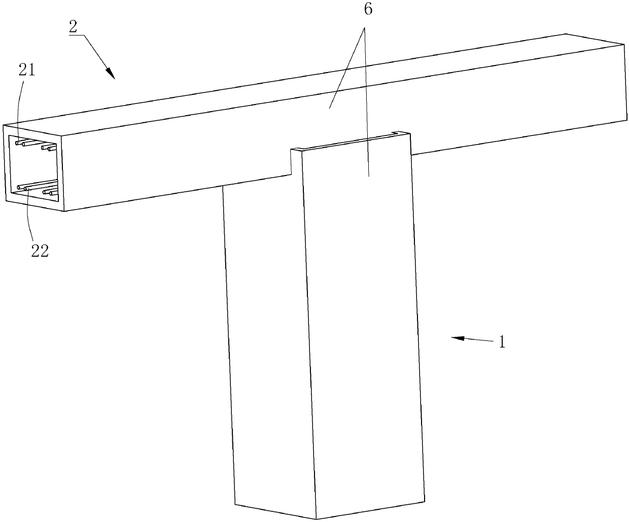
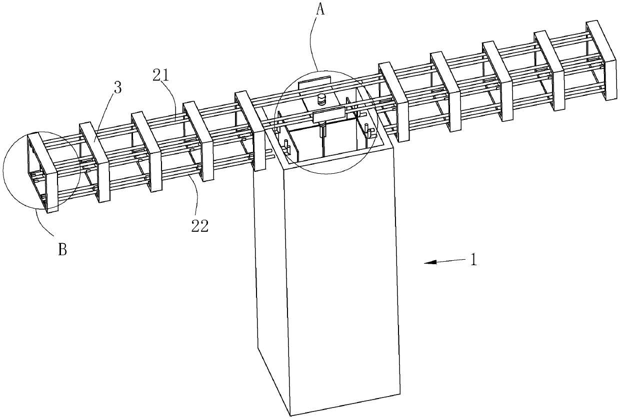
[0047] Such as Figure 1 to Figure 2 As shown, the anchorage structure of a concrete beam and a steel concrete column disclosed by the present invention includes a concrete column 1, a section steel 11 is embedded in the concrete column 1, a concrete beam 2 is connected between adjacent concrete beams 2, and the inner edge of the concrete beam 2 The concrete beam 2 is horizontally buried with an upper through-bar 21 and a lower longitudinal bar 22 , wherein the upper through-bar 21 is located above the lower longitudinal bar 22 . The upper through-bar 21 runs through the upper end of the concrete column 1 , and the height of the upper end of the shaped steel 11 is lower than that of the upper through-bar 21 so that the upper through-bar 21 does not contact the shaped steel 11 .

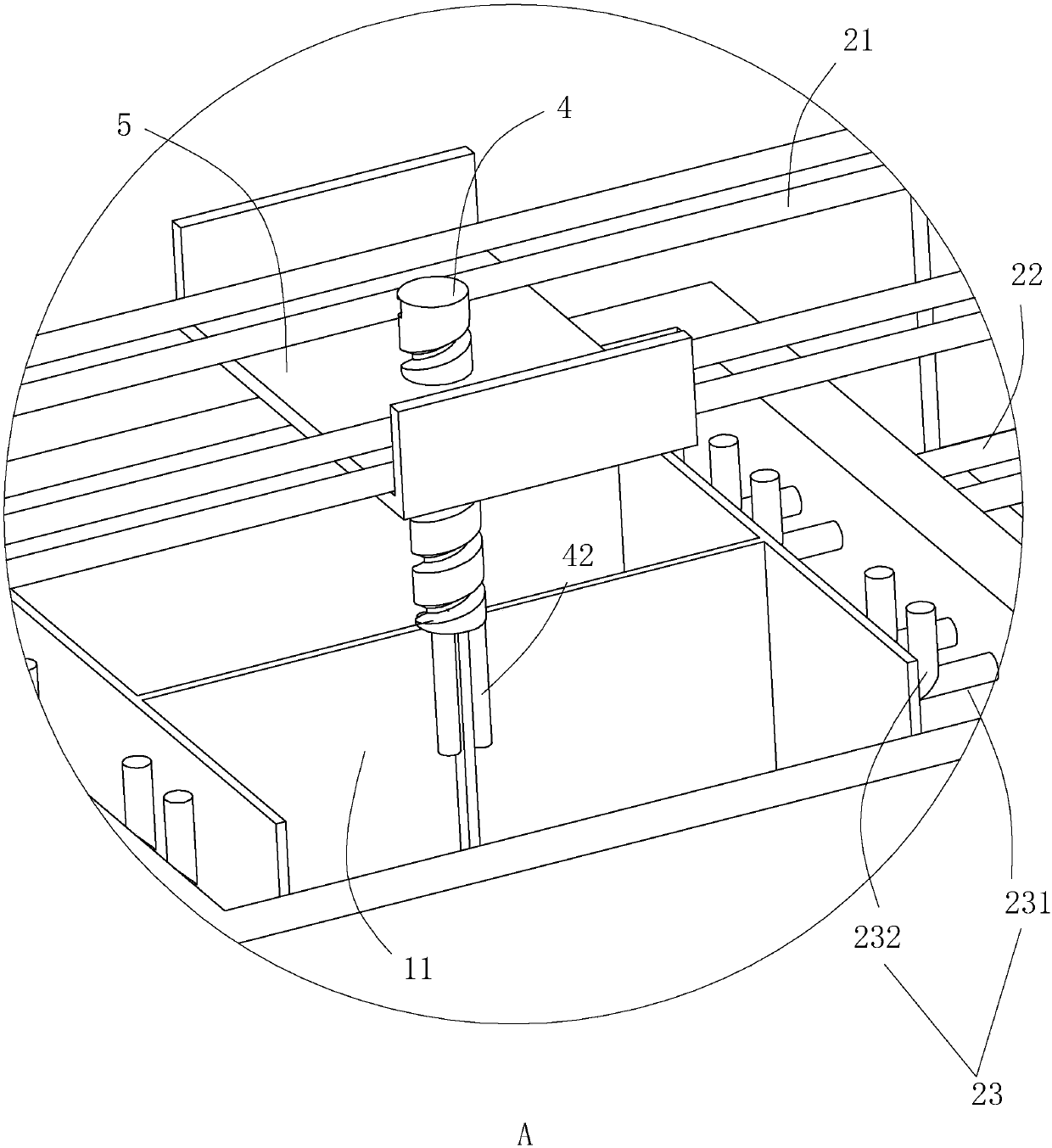
[0048] Such as image 3 As shown, the end of the lower longitudinal reinforcement 22 close to the concrete column 1 is fixed with a vertically upward curved hook 23, the bending angle of the hook 23 ...

Embodiment 2

[0059] Such as Figure 7 As shown, the difference between this embodiment and Embodiment 1 is that the bending section 232 is wave-shaped, thereby increasing the bonding area between the bending section 232 and the concrete of the concrete column 1 at the same height, and further The tensile performance of the concrete beam 2 is improved.


PUM


Abstract

The invention relates to an anchoring structure for concrete beams and steel reinforced concrete columns. The anchoring structure comprises the concrete columns, wherein profile steel is embedded in the concrete columns, the concrete beams are connected between the concrete columns, a plurality of upper through steel ribs and lower longitudinal ribs are embedded in the concrete beams, the end parts of the lower longitudinal ribs are provided with bent hooks, the bent hooks are embedded in the concrete columns, the upper through steel ribs penetrate through the concrete columns, and the heightof the upper end of the profile steel is smaller than that of the upper through steel ribs. By adopting the technical scheme, stress is the same no matter whether the lower longitudinal ribs on the two sides of the concrete columns penetrate through the profile steel or not, and stress weak spots are reduced for the profile steel when the lower longitudinal ribs do not penetrate through the profile steel. Since the end parts of the lower longitudinal ribs are provided with the bent hooks embedded in the concrete columns, the hogging moment resistance of the two ends of the concrete beams is improved, meanwhile, the lower longitudinal ribs are cooperated with the upper through steel ribs which penetrate through the concrete columns, and the sagging moment resistance of the middles of the concrete beams is improved.

Description

technical field [0001] The invention relates to the technical field of building construction, in particular to a concrete beam and steel concrete column anchorage structure and a construction method. Background technique [0002] At present, steel structures have been widely used in the field of super high-rise buildings and large-span space structures. Therefore, steel structures and concrete are mixed in many high-rise buildings, that is, the outer sides of steel columns are wrapped with concrete, which is what we usually call rigid steel structures. Since the concrete column is provided with profiled steel, the way of opening holes in the profiled steel is generally used to arrange the longitudinal reinforcement of the beam throughout the length, so as to improve the tensile performance of the beam. [0003] However, due to the way of opening holes in the section steel, the section steel forms a stress concentration area at the opening position, which reduces the compress...

Claims


Application Information

Patent Timeline
Patent Type & Authority Applications(China)
IPC IPC(8): E04B1/30E04B1/58E04G21/00
CPCE04B1/185E04B1/30E04G21/00
Inventor 金雪峰
Owner 广州市天作建筑规划设计有限公司
Why Eureka
Try Eureka