
Short-cylinder harmonic reducer with gap compensation function

A harmonic reducer and backlash compensation technology, which is applied to transmission parts, belts/chains/gears, mechanical equipment, etc., can solve problems such as improved processing technology requirements, low service life, and increased costs, so as to improve transmission accuracy, The effect of reducing the number of parts and increasing the service life

Active Publication Date: 2019-04-23
JIANGSU UNIV OF SCI & TECH
View PDF9 Cites 7 Cited by
  • Summary
  • Abstract
  • Description
  • Claims
  • Application Information

AI Technical Summary

Problems solved by technology

[0003] The above-mentioned patents use different structures to shorten the length of the reducer or realize the inter-tooth compensation function, but there are also obvious deficiencies: 1. Patent (1) is the main structural form of the current harmonic drive. The main problem of this structure is that the flexwheel Due to the particularity of the material, there are too many parts in the entire transmission, for example, multiple bolts are required between the inner and outer rings of the cross bearing and the rigid wheel and flexible wheel
2. Patent (2) Although the inter-tooth gap compensation is realized by arranging the tooth part as a flexible structure, the materials of the two sections on the same rigid wheel are different, resulting in increased processing technology requirements, increased costs, and insufficient rigidity of the flexible part. low life
3. Patent (3) realizes inter-tooth backlash compensation by adding an elastic compensation device on the wave generator, but the long-axis direction of the wave generator is elastic, which makes it difficult to average the force on the long axis and cause uneven wear between the teeth , will also accelerate the wear of the flexible gear

Method used


Image

  • Short-cylinder harmonic reducer with gap compensation function
  • Short-cylinder harmonic reducer with gap compensation function
  • Short-cylinder harmonic reducer with gap compensation function

Examples


Embodiment Construction

[0028] In the description of the present invention, it should be understood that the terms "center", "upper", "lower", "left", "right", etc., indicate the orientation or position relationship based on the orientation or position relationship shown in the drawings. It is only for the convenience and clarity of describing the present invention, rather than referring to the specific orientation of a specific device or part.

[0029] In the description of the present invention, it should be noted that, unless there are clear regulations and limitations, the terms "installation", "fixation" and "connection" shall be understood in a broad sense.

[0030] The present invention will be described in further detail below in conjunction with the drawings.

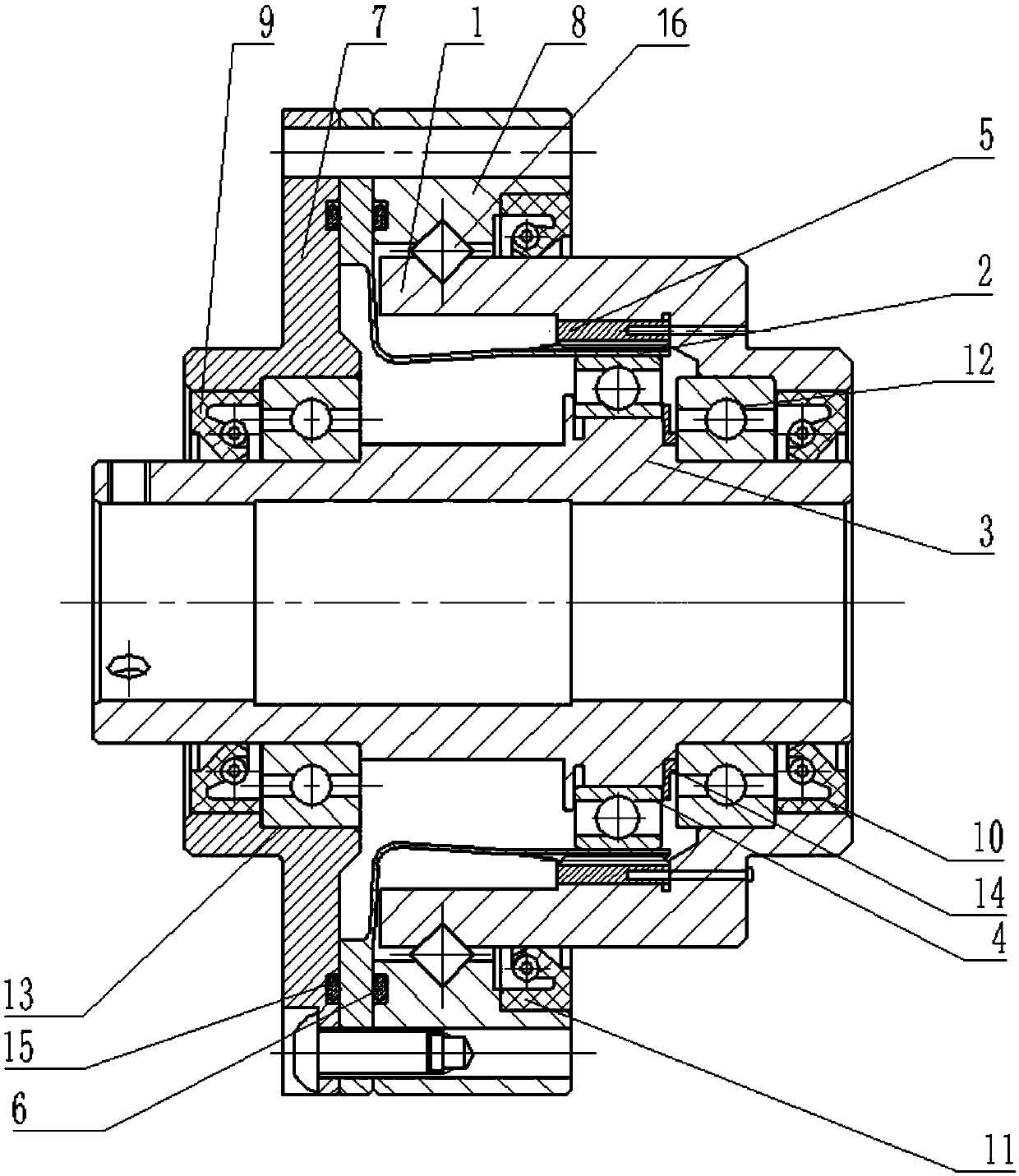
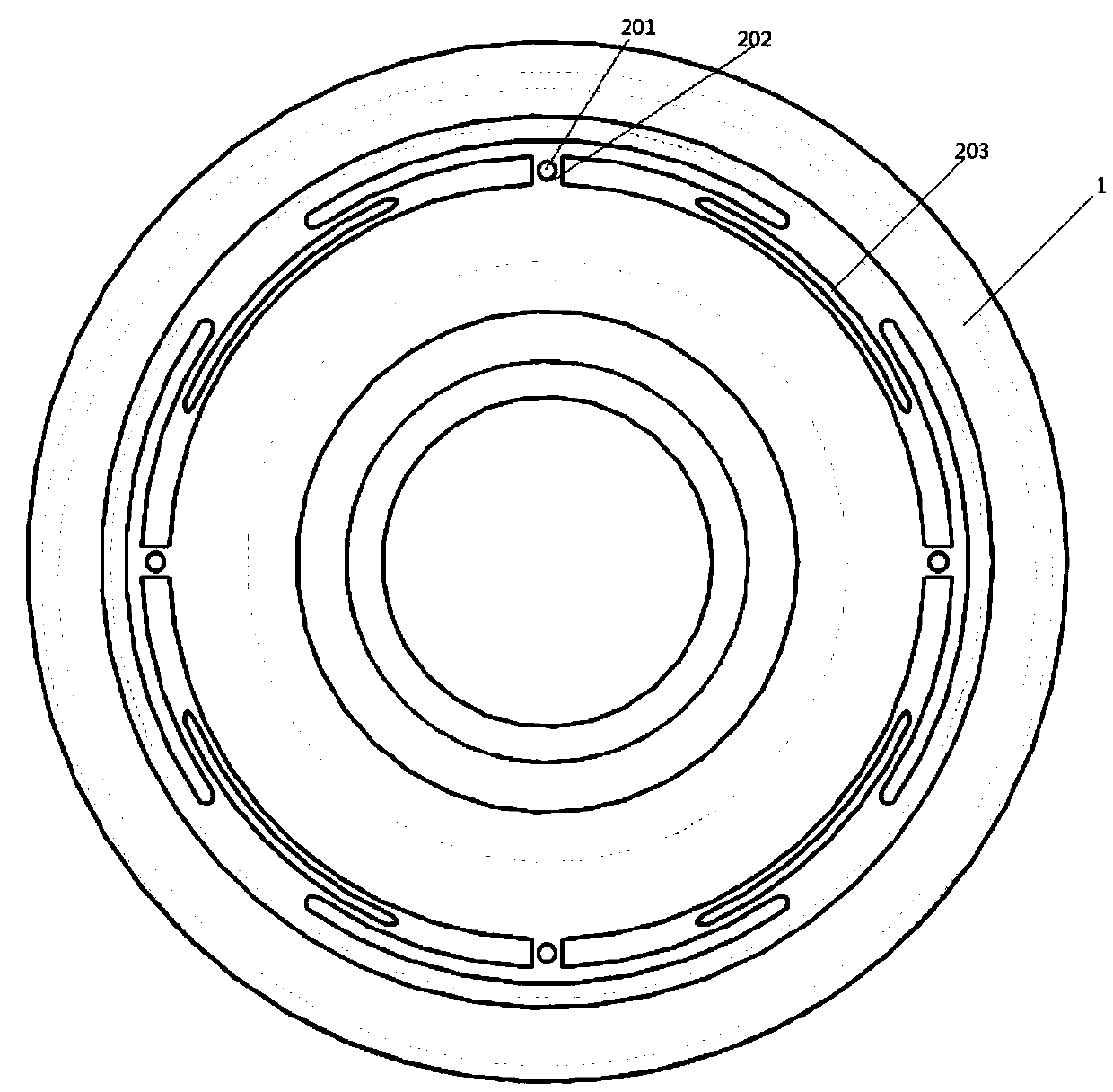
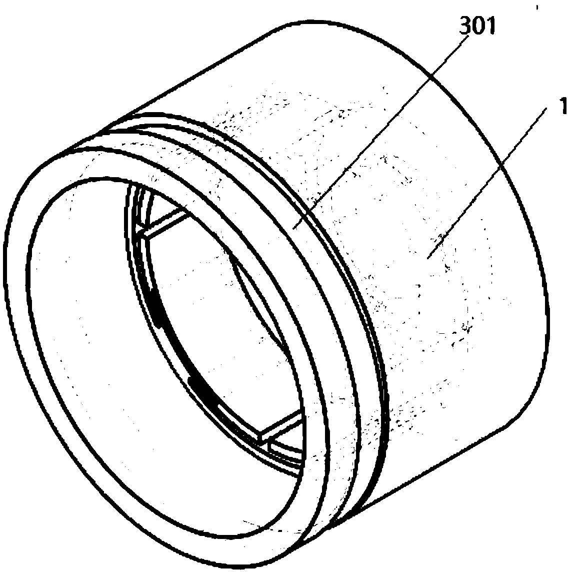
[0031] Such as Figure 1-Figure 6 Shown here is a short harmonic reducer with gap compensation function of the present invention, including a wave generator 3, on the elliptical circumference of the wave generator 3, a flexible bearing 4, a...


PUM


Abstract

The invention discloses a short-cylinder harmonic reducer with a gap compensation function. The reducer comprises a gear ring separation type rigid wheel, a wave generator and a flexible wheel. The gear ring separation type rigid wheel comprises a rigid wheel outer ring and a flexible inner gear ring, wherein an elastic compensation device which is provided with an arc-shaped groove in the surfaceand has a function of reducing a gap is arranged on the rigid wheel outer ring, the rigid wheel outer ring serves as an end cover and is installed on the wave generator through a roller bearing, theseparated rigid wheel outer ring is also used as an inner ring of a crossed roller bearing between the flexible wheel and the rigid wheel, the flexible inner gear ring is matched with the elastic compensation device and can be deformed along with long-axis movement of the wave generator, the gap compensation function is achieved, the inner gear ring and the rigid wheel outer ring are fixed throughlimiting, a flexible bearing is arranged on the wave generator, a flexible bearing outer ring and a flexible wheel inner ring are tightly pressed, gear teeth of the flexible wheel are meshed with gear teeth of the flexible inner gear ring, and the flexible wheel and an outer ring of the crossed roller bearing are fixed into a whole. According to the reducer, the length of the reducer is reduced,the structure is compact, the gap compensation function is further achieved, so that the service life is prolonged, and the transmission precision is improved.

Description

Technical field [0001] The invention relates to a harmonic reducer, and specifically designs a short-tube harmonic reducer with a short structure and a backlash compensation function. Background technique [0002] The harmonic gear reducer is composed of a fixed internal tooth rigid wheel, a flexible wheel, and a wave generator that deforms the flexible wheel radially. The harmonic drive reducer has the advantages of large transmission ratio, wide range, small size, light weight, and large transmission ratio. A literature search on the prior art found: (1) Chinese Patent Publication Number: CN 107339402A, Announcement Date: 2017.11.10, and the patent name: Harmonic Reducer. This patent describes a harmonic reducer. The rigid wheel and the flexible wheel are connected by cross-roller bearings, with compact structure, flexible design, small size and light weight. (2) Chinese patent publication number: CN 107795662A, announcement date: 2018.03.13, the patent name is: rigid wheel f...

Claims


Application Information

Patent Timeline
Patent Type & Authority Applications(China)
IPC IPC(8): F16H49/00F16H57/023F16H57/12
CPCF16H49/001F16H57/023F16H57/12
Inventor 王淑妍杨超凡吕渌渊单晨
Owner JIANGSU UNIV OF SCI & TECH
Learn More