Defrosting control method and system for heat pump unit

A technology of heat pump unit and control method, applied in refrigerators, refrigeration components, refrigeration and liquefaction, etc., can solve the problems of reduced heat exchange efficiency, influence of unit capacity, inability to guarantee the operation performance of heat pump units, etc., and achieve the effect of precise defrosting

Active Publication Date: 2019-04-23
GUANGDONG PHNIX ECO ENERGY SOLUTION
View PDF7 Cites 6 Cited by
  • Summary
  • Abstract
  • Description
  • Claims
  • Application Information

AI Technical Summary

Problems solved by technology

[0002] When the heat pump system is heating, when the ambient temperature is lower than the freezing point, the water vapor in the air will condense into a frost layer on the surface of the heat exchanger. The frost layer not only directly increases the heat transfer resistance of the heat exchanger, but also makes it pass through Reduced air flow through the heat exchanger, resulting in less efficient heat transfer, necessitating action to defrost
[0003] At present, the defrosting of heat pump units usually adopts two methods: timing defrosting or intelligent defrosting: 1. Timing defrosting is based on a specified defrosting time, and defrosting will be carried out when the specified defrosting time is reached. If the specified defrosting time is too short, the capacity of the unit will be affected, and if it is too long, the defrosting will be unclean; 2. At present, the smart defrosting of heat pumps usually uses the ratio of temperature and pressure to judge defrosting. However, this control The defrosting effect is often affected by the detection accuracy of the temperature / pressure sensor, and the best operating performance of the heat pump unit cannot be guaranteed while defrosting

Method used


Image

  • Defrosting control method and system for heat pump unit
  • Defrosting control method and system for heat pump unit
  • Defrosting control method and system for heat pump unit

Examples


Embodiment Construction

[0071] The implementation of the present invention is described below through specific examples and in conjunction with the accompanying drawings, and those skilled in the art can easily understand other advantages and effects of the present invention from the content disclosed in this specification. The present invention can also be implemented or applied through other different specific examples, and various modifications and changes can be made to the details in this specification based on different viewpoints and applications without departing from the spirit of the present invention.

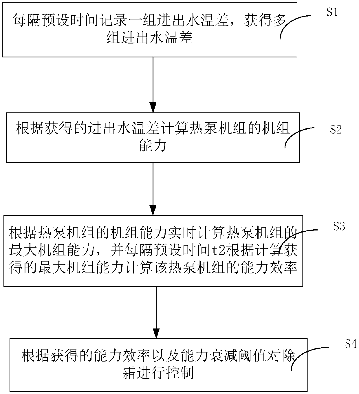
[0072] figure 1 It is a flow chart of steps of a defrosting control method for a heat pump unit according to an embodiment of the present invention. Such as figure 1 As shown, a defrosting control method of a heat pump unit in the present invention includes the following steps:

[0073] Step S1, every preset time t 1 Record a set of inlet and outlet water temperature differences, and obt...


PUM


Abstract

The invention discloses a defrosting control method and system for a heat pump unit. The defrosting control method comprises the following steps that S1, a set of water inlet and outlet water temperature difference is recorded every preset time t1, and a plurality of groups of water inlet and outlet temperature difference delta t water i are obtained; S2, the unit capacity delta capability of theheat pump unit is calculated according to the obtained water inlet and outlet temperature difference; S3, the maximum unit capacity max (delta capacity) of the heat pump unit is calculated in real time according to the unit capacity delta capability of the heat pump unit, and the maximum unit capacity max (delta capacity) obtained according to calculation is calculated every preset time t2, and the capacity efficiency delta capability efficiency of the heat pump unit is calculated; and S4, a defrosting program is determined according to the obtained capability efficiency delta capability efficiency and the capacity attenuation threshold value, and defrosting control is carried out. According to the defrosting control method and system for the heat pump unit, the optimal unit performance ofthe heat pump unit can be guaranteed while accurate defrosting is met.

Description

technical field [0001] The invention relates to the technical field of heat pump control, in particular to a defrosting control method and system of a heat pump unit capable of realizing optimal unit performance. Background technique [0002] When the heat pump system is heating, when the ambient temperature is lower than the freezing point, the water vapor in the air will condense into a frost layer on the surface of the heat exchanger. The frost layer not only directly increases the heat transfer resistance of the heat exchanger, but also makes it pass through Reduced air flow through the heat exchanger results in a less efficient heat exchange, so measures need to be taken to defrost. [0003] At present, the defrosting of heat pump units usually adopts two methods: timing defrosting or intelligent defrosting: 1. Timing defrosting is based on a specified defrosting time, and defrosting will be carried out when the specified defrosting time is reached. If the specified de...

Claims


Application Information

Patent Timeline
Patent Type & Authority Applications(China)
IPC IPC(8): F25B47/00F25B49/00
CPCF25B47/00F25B49/00F25B2600/01F25B2700/21
Inventor 雷朋飞黄世哲叶景发刘远辉高翔刘辉吴思朗吴东华朱晓广廖立元刘志力梁华锋
Owner GUANGDONG PHNIX ECO ENERGY SOLUTION
Why Eureka
Try Eureka