
Electric compressor motor stator and manufacturing method thereof

A technology of electric compressors and motor stators, applied in the manufacture of motor generators, electromechanical devices, electric components, etc., can solve the problems of increased motor vibration and noise, low stator slot fullness, and reduced work efficiency, so as to reduce vibration and noise, reduce cogging torque, and improve winding efficiency

Pending Publication Date: 2019-04-23
苏州新智机电工业有限公司
View PDF0 Cites 4 Cited by
  • Summary
  • Abstract
  • Description
  • Claims
  • Application Information

AI Technical Summary

Problems solved by technology

This structure has the following problems: 1) The stator slot full ratio is low, which reduces the power density of the motor and increases the size and weight of the motor; 2) There is a gap between adjacent teeth, which causes magnetic flux leakage and reduces work efficiency. At the same time, cogging torque will be brought, which will increase the vibration and noise during the operation of the motor; 3) The winding is wound in an inner winding method, which is inconvenient to wind and takes a long time to wind, which reduces production efficiency and increases production costs

Method used


Image

  • Electric compressor motor stator and manufacturing method thereof
  • Electric compressor motor stator and manufacturing method thereof
  • Electric compressor motor stator and manufacturing method thereof

Examples


Embodiment Construction

[0025] Below in conjunction with accompanying drawing this patent is described further.

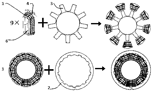
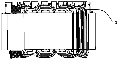
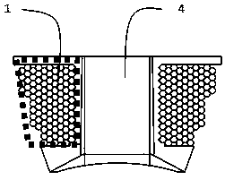
[0026] Such as Figure 1~Figure 8 As shown, an electric compressor motor stator, its structure includes a stator winding 1, a stator yoke 2, a stator tooth 3, a stator skeleton 4, and a stator coil 6; wherein the bottoms of nine stator teeth 3 are connected to each other to form The distance between each stator tooth part 3 on the ring is the same, and the outer part of the stator tooth part 3 is covered with a circular stator yoke part 2; each stator tooth part 3 is provided with an independent stator Coils 6 , each independent stator coil 6 is formed by winding three turns of stator winding 1 on one stator skeleton 4 .

[0027] The number of the stator teeth 3 is 9, and each stator tooth 3 includes a tooth 30, a bridge 31, a tooth root 32, a tooth crown 33, and a tooth 34; wherein the top of the tooth 30 is provided with a tooth root 32, and the teeth Both sides of the root 32 are pro...


PUM


Abstract

The invention provides an electric compressor motor stator and a manufacturing method thereof. The electric compressor motor stator comprises a stator winding, stator tooth parts, a stator yoke part and a stator framework, and is characterized in that a stator iron core comprises the stator tooth parts and the stator yoke part, which are separated from each other; the stator tooth parts are connected through bridges; the stator winding is orderly wound on the stator framework; lead wires at two ends of the winding are fixed on a fixed pin; a winding process can be independently finished; afterthe winding is finished, assembling holes on the stator winding and the stator framework are directly assembled on teeth; after each tooth on a stator part is assembled, a tooth root of each of the stator tooth part and a clamping groove of the stator yoke part are matched to finish installation. The electric compressor motor stator provided by the invention has the advantages that a production technology of the motor stator is simplified; the stator winding is independently wound on the framework, the arrangement is ordered and the production efficiency is high; the slot space factor of thestator is high and the energy density of a motor is improved; a closed groove is designed so that the flux leakage is reduced and the operation vibration and noises are reduced.

Description

technical field [0001] The invention relates to an electric compressor motor stator and a manufacturing method thereof, belonging to the technical field of electric compressor motor manufacturing. Background technique [0002] At present, most motor stator teeth and yokes are integrally formed. A gap is reserved between the adjacent tooth crowns, so that the nozzle can penetrate up and down to wind the winding on the stator teeth. This structure has the following problems: 1) The stator slot full ratio is low, which reduces the power density of the motor and increases the size and weight of the motor; 2) There is a gap between adjacent teeth, which causes magnetic flux leakage and reduces work efficiency. At the same time, cogging torque will be brought, which will increase the vibration and noise during the operation of the motor; 3) The winding is wound by the inner winding method, which is inconvenient to wind and takes a long time to wind, which reduces production effic...

Claims


Application Information

Patent Timeline
Patent Type & Authority Applications(China)
IPC IPC(8): H02K1/14H02K3/52H02K15/095
CPCH02K1/146H02K3/522H02K15/095
Inventor 李江姚奕王杨扬
Owner 苏州新智机电工业有限公司
Learn More